Ever since upgrading the 3D printer to the Ultimaker 2+ I've had issues with prints warping and detaching from the build plate.
Today I finally twigged what was different between before and after the upgrade. The 2+ kit came with a calibration card for bed levelling.
I've measured the thickness of the card against the thickness of the paper I used to use. The paper is 0.03mm thinner at 0.12mm thick. Not only that but the new coated card has also picked up a thin layer of plastic in places from the nozzle so the thickness is no longer consistent, at one point is was 0.20mm thick compared to the average 0.15mm. The paper, despite having been in use for two years, does not have anything attached to its surface.
I've gone back to my thinner paper calibration and the first print is still attached to the bed.
I do not use any adhesive on my glass. I keep it clean with an imitation chamois leather and very occasionally degrease it with isopropyl alcohol.
I also made a change to the design of the model to add expansion gaps so that the shrinking plastic cannot pull the full width of the model.
Search This Blog
Saturday, 12 August 2017
Fusion 360 beginner tips
If I leave this page until I am an expert I will have forgotten what I found difficult when I just started.
Hence this page. As much a reminder for myself as a guide for others.
There are lots of video tutorials on the Fusion 360 site but harder to find are some handy reference pages covering most topics:
http://help.autodesk.com/view/fusion360/ENU/?guid=GUID-18445C60-F9AD-4217-8066-CA48FA11E514
Navigation
I find the use of the middle mouse button for Pan and Tilt unreliable. This is not specific to Fusion 360 I have the same problem in Blender. I prefer to use the keyboard in Blender but Fusion 360 has some very handy buttons at the bottom of the screen which means you can even work with a touch pad.
Click on the Pan and Tilt or the move icons and use the mouse with the normal button. Press the Escape key to exit that mode.
In addition the top right corner has a cube and you can select the faces or corners or other bits to get a quick rotation to the view you want and it is always clear which way you are looking even if your model happens to be completely symmetrical.
I find that cube the most useful.
Finding your work
This took me a minute or two.
To get back to your saved work you need to open up the left side panel using the icon in the very top left corner as highlighted in the above image.
Making changes
This was fairly clearly documented but worth repeating. When you open up your sketch it will be in a view mode.
To make changes you will need to select the script in the list and select edit.
When you have finished editing and want to see the result in 3D, use the Stop Sketch button.
Selecting Edges and Faces
You can add features that are not part of the model but used as the basis for calculating other parts of the model.
Like construction lines in hand drawn work.
This allow you to mark centres and position things parallel to faces.
Models, bodies and Patches
Models are made of bodies and patches. Those can be calculated from sketches, created from basic shapes, imported or manually modelled.
The main difference between a body and a patch is that a body must always be solid but a patch can just be a disconnected collection of faces.
Bodies - Solid manifold objects.
Patches - Do not have to be solid.
Only solid bodies can be used for cuts and joints.
Patches will automatically convert to a body if they are stitched together, using the stitch command or the holes between their faces are covered using other patches and planes.
Components
A component is any pre-existing model that you include in your design.
Models within your design can be converted to components.
Existing designs can be dragged from the file browser in to your design.
A component has it's own time line and can be edited separately from the rest of the design.
The components I have created retain their own orientation which gets a bit confusing when trying to move or rotate them. There is a method to capture their position [which I am not sure how to do yet.]
To edit a component. Activate it in the object browser.
To go back to the main design. Activate the top level item in the object browser.
3D Printing and STL files
There is an option on the save menu called 3D print and you can use a workflow designed by Autodesk that I have not investigated. From there you can deselect the Output to 3D print and it will save as an STL.
That's how I first started to get my models to save as STL but I now prefer the other option I came across.
Once you have joined all your bodies in to one body you can export to STL from the Browser list.
Right click on the body you want to export and select 'Save As STL'
A very similar dialogue box to the 3D print dialogue appears but defaulting to save as an STL.
Axes Z up or Y up
My 3D printer works with the Z axis up and down, X sideways and Y back to front.
Ideally, that's how I create my models.
You can change the axes direction in your preferences within Fusion 360.
Keyboard Shortcuts
There are several guides to what keyboard commands are available within Fusion 360 so I won't reproduce the whole table, just refer to one of the following guides:
http://www.cadforum.cz/cadforum_en/keyboard-shortcuts-in-autodesk-fusion-360-tip10167
https://www.autodesk.com/shortcuts/fusion-360
Mouse Control
For using a touch pad or trackball, I have found that it is easier using the Autodesk Inventor Pan, Zoom and Orbit controls.
I typed up a short article:
http://blog.discoverthat.co.uk/2019/01/fusion-360-zoom-pan-and-orbit.html
==
Special Care
Many functions work about the origin or a manually added construction element.
I could not find a way to automatically centre a model on the origin. You can move it manually but each group of faces needs to be selected and moved.
Tip: When you start always create your main section central to the origin.
For symmetrical models that you intend to mirror or rotate, starting with one corner on the origin may be appropriate.
==
Things I Could NOT Find
In such a professional looking product there were some features that I expected but that I could not find at all. In many cases I even found feature requests from as far back as 2013 and yet today in 2017 I could still not find the feature!
If anyone knows how to do these please post a comment to let me know how.
* Repeating Groups of Faces on other Faces [no idea how]
I can copy the feature as a group of faces and I can copy sketch elements but I could not find a way to use a parameter to repeat a feature on each face.
If I copy the faces I cannot find a way to line up one face to exactly touch another face. I had to rely on the grid snap. I might be able to mirror the features. I think I will need to create an exactly central construction line.
* Wrap a shape round another shape [Feature request]
According to this forum post this is a requested feature but not implemented, as at Feb 2017.
There are features being added to the sheet metal section as previewed in another post.
==
I will add to this post as I find other features worth noting.
Hence this page. As much a reminder for myself as a guide for others.
There are lots of video tutorials on the Fusion 360 site but harder to find are some handy reference pages covering most topics:
http://help.autodesk.com/view/fusion360/ENU/?guid=GUID-18445C60-F9AD-4217-8066-CA48FA11E514
Navigation
I find the use of the middle mouse button for Pan and Tilt unreliable. This is not specific to Fusion 360 I have the same problem in Blender. I prefer to use the keyboard in Blender but Fusion 360 has some very handy buttons at the bottom of the screen which means you can even work with a touch pad.
Click on the Pan and Tilt or the move icons and use the mouse with the normal button. Press the Escape key to exit that mode.
In addition the top right corner has a cube and you can select the faces or corners or other bits to get a quick rotation to the view you want and it is always clear which way you are looking even if your model happens to be completely symmetrical.
I find that cube the most useful.
Finding your work
This took me a minute or two.
To get back to your saved work you need to open up the left side panel using the icon in the very top left corner as highlighted in the above image.
Making changes
This was fairly clearly documented but worth repeating. When you open up your sketch it will be in a view mode.
To make changes you will need to select the script in the list and select edit.
When you have finished editing and want to see the result in 3D, use the Stop Sketch button.
Selecting Edges and Faces
- Select one edge or face
left click on the edge or the face. - Select a narrow face
Zoom in until moving the mouse over the face changes the colour of the whole face. Then click. - Select multiple edges or faces
Hold down CTRL and left click on each element. - Select an edge loop
Double click any edge in the loop. - Group faces
Right click on the browser, choose, Create selection Set.
Select multiple faces.
Use the icon on the newly created selection set to assign the faces to that set.
Use the other icon when you want to select those faces.
You can add features that are not part of the model but used as the basis for calculating other parts of the model.
Like construction lines in hand drawn work.
This allow you to mark centres and position things parallel to faces.
Models, bodies and Patches
Models are made of bodies and patches. Those can be calculated from sketches, created from basic shapes, imported or manually modelled.
The main difference between a body and a patch is that a body must always be solid but a patch can just be a disconnected collection of faces.
Bodies - Solid manifold objects.
Patches - Do not have to be solid.
Only solid bodies can be used for cuts and joints.
Patches will automatically convert to a body if they are stitched together, using the stitch command or the holes between their faces are covered using other patches and planes.
- Create menu - adds a new body.
- Modify menu - makes changes to an existing body.
Components
A component is any pre-existing model that you include in your design.
Models within your design can be converted to components.
Existing designs can be dragged from the file browser in to your design.
A component has it's own time line and can be edited separately from the rest of the design.
The components I have created retain their own orientation which gets a bit confusing when trying to move or rotate them. There is a method to capture their position [which I am not sure how to do yet.]
To edit a component. Activate it in the object browser.
To go back to the main design. Activate the top level item in the object browser.
3D Printing and STL files
There is an option on the save menu called 3D print and you can use a workflow designed by Autodesk that I have not investigated. From there you can deselect the Output to 3D print and it will save as an STL.
That's how I first started to get my models to save as STL but I now prefer the other option I came across.
Once you have joined all your bodies in to one body you can export to STL from the Browser list.
Right click on the body you want to export and select 'Save As STL'
A very similar dialogue box to the 3D print dialogue appears but defaulting to save as an STL.
Axes Z up or Y up
My 3D printer works with the Z axis up and down, X sideways and Y back to front.
Ideally, that's how I create my models.
You can change the axes direction in your preferences within Fusion 360.
Keyboard Shortcuts
There are several guides to what keyboard commands are available within Fusion 360 so I won't reproduce the whole table, just refer to one of the following guides:
http://www.cadforum.cz/cadforum_en/keyboard-shortcuts-in-autodesk-fusion-360-tip10167
https://www.autodesk.com/shortcuts/fusion-360
Mouse Control
For using a touch pad or trackball, I have found that it is easier using the Autodesk Inventor Pan, Zoom and Orbit controls.
I typed up a short article:
http://blog.discoverthat.co.uk/2019/01/fusion-360-zoom-pan-and-orbit.html
==
Special Care
- Centre your model about the origin.
Many functions work about the origin or a manually added construction element.
I could not find a way to automatically centre a model on the origin. You can move it manually but each group of faces needs to be selected and moved.
Tip: When you start always create your main section central to the origin.
For symmetrical models that you intend to mirror or rotate, starting with one corner on the origin may be appropriate.
==
Things I Could NOT Find
In such a professional looking product there were some features that I expected but that I could not find at all. In many cases I even found feature requests from as far back as 2013 and yet today in 2017 I could still not find the feature!
If anyone knows how to do these please post a comment to let me know how.
* Repeating Groups of Faces on other Faces [no idea how]
I can copy the feature as a group of faces and I can copy sketch elements but I could not find a way to use a parameter to repeat a feature on each face.
If I copy the faces I cannot find a way to line up one face to exactly touch another face. I had to rely on the grid snap. I might be able to mirror the features. I think I will need to create an exactly central construction line.
* Wrap a shape round another shape [Feature request]
According to this forum post this is a requested feature but not implemented, as at Feb 2017.
There are features being added to the sheet metal section as previewed in another post.
==
I will add to this post as I find other features worth noting.
Friday, 11 August 2017
Fusion 360 for 3D printing
I've only been using Fusion 360 for a day and already I am convinced that it is a very good tool for creating models to 3D print.
Autodesk have created an application designed for engineering. The starting point is a sketch, like you would draw on a bit of paper but this is online. You don't need to worry about exact sizes to start with because once you have your starting point you can dimension each edge and the shape adjusts to those sizes, angles and formulae that you enter.
In just a few hours I have recreated a model that I had recently printed. That time spent included learning how to use each feature I needed as I went. I watched a few starter videos and read a few of the beginner reference pages from the AutoDesk web site. The results of just a little effort are already very usable.
Having a little bit of AutoCAD knowledge may have helped because some of the interface was vaguely familiar. Getting my head round the construction and formulaic way of working probably took me the longest.
Unlike the vertex modelling that I am used to with Blender, Fusion 360 is a mathematical construction tool. Create shapes, called bodies, which can be used as part of the finished model or as a construction component to cut away at other bodies to leave the shape you want. Just hide the construction from the finished model. Parts can be kept as separate components or binary joined so they make a single object, ideal for 3D printing.
The construction lines and objects are still there, but not part of the finished object. If you change any dimension all those construction elements remain in the calculations so you can make changes to any part of the model and the finished object adjusts based on the way you have built it.
This makes changing things like lengths and thicknesses very easy.
The end result for 3D printing was very tidy.
I was a little sceptical about using an online application but it is still installed locally and in the event of an Internet outage saves files locally until the connection is re-established.
Files can also be deliberately archived locally or exported to a short list of other file types, if desired.
The only issues I've had probably relate to pushing the USB dock a bit hard. I use that with my laptop. It's not an ideal setup for 3D graphics work but it's done the job regardless most of the time.
Fortunately, for us home 3D printing enthusiasts, AutoDesk have made Fusion 360 available for free to hobby and education users and even very small businesses.
The implication from the wording is that it will remain free otherwise I would not be using it.
==
Update: One year on
I started to a see a countdown that the licence would end in x number of days time.
I was sure I had already signed up to a hobby, enthusiast account but I guess that needs to be renewed each year. The licensing terms are not clear on this.
I used the instructions on the following web page:
https://knowledge.autodesk.com/support/fusion-360/troubleshooting/caas/sfdcarticles/sfdcarticles/How-to-activate-start-up-or-educational-licensing-for-Fusion-360.html
Where it previously had a count down in the title bar it now says '(Startup License)'.
I'm pretty sure licence, in this context should be spelt with a 'C' towards the end, not an 'S'. Probably an American thing.
==
Autodesk have created an application designed for engineering. The starting point is a sketch, like you would draw on a bit of paper but this is online. You don't need to worry about exact sizes to start with because once you have your starting point you can dimension each edge and the shape adjusts to those sizes, angles and formulae that you enter.
In just a few hours I have recreated a model that I had recently printed. That time spent included learning how to use each feature I needed as I went. I watched a few starter videos and read a few of the beginner reference pages from the AutoDesk web site. The results of just a little effort are already very usable.
Having a little bit of AutoCAD knowledge may have helped because some of the interface was vaguely familiar. Getting my head round the construction and formulaic way of working probably took me the longest.
Unlike the vertex modelling that I am used to with Blender, Fusion 360 is a mathematical construction tool. Create shapes, called bodies, which can be used as part of the finished model or as a construction component to cut away at other bodies to leave the shape you want. Just hide the construction from the finished model. Parts can be kept as separate components or binary joined so they make a single object, ideal for 3D printing.
The construction lines and objects are still there, but not part of the finished object. If you change any dimension all those construction elements remain in the calculations so you can make changes to any part of the model and the finished object adjusts based on the way you have built it.
This makes changing things like lengths and thicknesses very easy.
The end result for 3D printing was very tidy.
I was a little sceptical about using an online application but it is still installed locally and in the event of an Internet outage saves files locally until the connection is re-established.
Files can also be deliberately archived locally or exported to a short list of other file types, if desired.
The only issues I've had probably relate to pushing the USB dock a bit hard. I use that with my laptop. It's not an ideal setup for 3D graphics work but it's done the job regardless most of the time.
Fortunately, for us home 3D printing enthusiasts, AutoDesk have made Fusion 360 available for free to hobby and education users and even very small businesses.
The implication from the wording is that it will remain free otherwise I would not be using it.
==
Update: One year on
I started to a see a countdown that the licence would end in x number of days time.
I was sure I had already signed up to a hobby, enthusiast account but I guess that needs to be renewed each year. The licensing terms are not clear on this.
I used the instructions on the following web page:
https://knowledge.autodesk.com/support/fusion-360/troubleshooting/caas/sfdcarticles/sfdcarticles/How-to-activate-start-up-or-educational-licensing-for-Fusion-360.html
Where it previously had a count down in the title bar it now says '(Startup License)'.
I'm pretty sure licence, in this context should be spelt with a 'C' towards the end, not an 'S'. Probably an American thing.
==
Tuesday, 8 August 2017
Socket set continuation
I have continued to evolve the the arrangement and storage segments for my socket set that I started a few weeks ago.
I've tried to incorporate a support shelf for the smaller internal tool cases.
This has led to the spanner rack taking a lot longer to print and I've had a few failures.
I am confident it will print more reliably if I slow down the printing speed. That would mean that as one piece it would now spend two days on the printer.
I'm not keen on such a long time printing. The slightest error and the whole thing has to be started again!
To reduce the risk, I have split it in to two pieces with dovetail joints to hold it together. I have also included holes to allow me to pin it with nails. The nails are probably unnecessary but no harm allowing the option.
I've also added a thin pouch within the handle of the case. This was primarily to help align the case halves when closing it.
It's worked well.
The case is now complete.
I've tried to incorporate a support shelf for the smaller internal tool cases.
This has led to the spanner rack taking a lot longer to print and I've had a few failures.
I am confident it will print more reliably if I slow down the printing speed. That would mean that as one piece it would now spend two days on the printer.
I'm not keen on such a long time printing. The slightest error and the whole thing has to be started again!
To reduce the risk, I have split it in to two pieces with dovetail joints to hold it together. I have also included holes to allow me to pin it with nails. The nails are probably unnecessary but no harm allowing the option.
I've also added a thin pouch within the handle of the case. This was primarily to help align the case halves when closing it.
It's worked well.
The case is now complete.
Monday, 7 August 2017
Ride height sensor connectors
When checking under the Discovery, I noticed that the connector housing is missing for one of the air suspension ride height sensors.
It appears to still be working OK so I've wrapped some tape round it for now. I would like to fix it properly at some point so I've been on a hunt for the connector.
It's a quite unique shape. With a little bit of research I'm fairly sure it is from the Micro Quadlok range, see the following from the manufacturer's site:
Housing: http://www.te.com/usa-en/product-1-967616-1.html
Contact pin: http://www.te.com/usa-en/product-1740336-1.html
Seal: http://www.te.com/usa-en/product-967056-1.html
They are available from RS Components with the associated components:
http://uk.rs-online.com/web/p/automotive-connectors/6801464/
http://uk.rs-online.com/web/p/automotive-connector-accessories/7180712/
http://uk.rs-online.com/web/p/automotive-connector-accessories/6802455/
Spelt in two different ways, so it needed multiple searches on the web site:
http://uk.rs-online.com/web/c/connectors/power-connectors/automotive-connector-accessories/?searchTerm=micro%20quadlok
http://uk.rs-online.com/web/c/connectors/power-connectors/automotive-connectors/?searchTerm=quadlock
I've also found a kit on e-bay which will be easier to buy but a bit more expensive:
http://www.ebay.co.uk/itm/Discovery-2-SLS-Air-Suspension-Ride-Height-Sensors-Harness-Connector-FREEPOST/172253397501
The clips that hold it on to the ride height sensor are a pain to get off so I have not yet managed to get the good one off. Once I have one in my hand to see close up, I'll practice releasing the latches before I have a go at the car again.
It appears to still be working OK so I've wrapped some tape round it for now. I would like to fix it properly at some point so I've been on a hunt for the connector.
It's a quite unique shape. With a little bit of research I'm fairly sure it is from the Micro Quadlok range, see the following from the manufacturer's site:
Housing: http://www.te.com/usa-en/product-1-967616-1.html
Contact pin: http://www.te.com/usa-en/product-1740336-1.html
Seal: http://www.te.com/usa-en/product-967056-1.html
They are available from RS Components with the associated components:
http://uk.rs-online.com/web/p/automotive-connectors/6801464/
http://uk.rs-online.com/web/p/automotive-connector-accessories/7180712/
http://uk.rs-online.com/web/p/automotive-connector-accessories/6802455/
Spelt in two different ways, so it needed multiple searches on the web site:
http://uk.rs-online.com/web/c/connectors/power-connectors/automotive-connector-accessories/?searchTerm=micro%20quadlok
http://uk.rs-online.com/web/c/connectors/power-connectors/automotive-connectors/?searchTerm=quadlock
I've also found a kit on e-bay which will be easier to buy but a bit more expensive:
http://www.ebay.co.uk/itm/Discovery-2-SLS-Air-Suspension-Ride-Height-Sensors-Harness-Connector-FREEPOST/172253397501
The clips that hold it on to the ride height sensor are a pain to get off so I have not yet managed to get the good one off. Once I have one in my hand to see close up, I'll practice releasing the latches before I have a go at the car again.
Friday, 4 August 2017
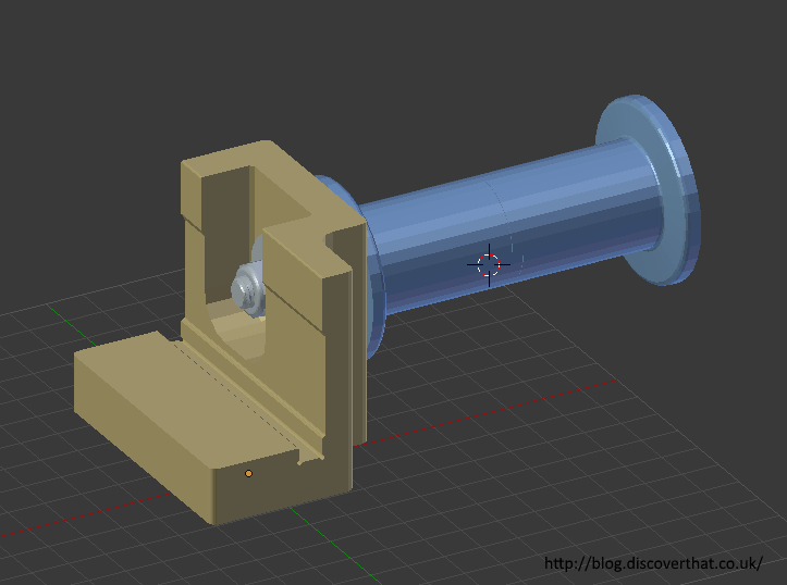
Filament spool spindle
If you refer back to some of my earlier posts about the Ultimaker and feeding filament, you will know that I think the friction from the spool often causes under-extrusion. I have a further idea to reduce the drag.
This is a spindle for the spool with bearings in. There are loads of designs available that do the same thing. Most involve clamping the spool in some way to a spindle containing bearings.
I like to be able to easily lift the spool on and off. I see no advantage in a complex clamp. Before creating this my spools just loosely hooked on a fixed shaft. A bit looser than the original clip in spindle which is very fiddly to work with. This design is just an evolution of the hook but with bearings to make the spindle run freely.
This has worked very well the spool spins freely.
Bill of materials:
1x M8x110mm bolt
1x M8 nylon locknut
2x M8 Form A (normal) washers
1x M8x25mm or penny washer
3x 8mm axle 22mm x7mm bearings (from skates)
Optional:
2x 10mm O/D x1mm thick lengths of aluminium tube cut to fit as spacers between the bearings
The 3D printed parts:
1x Hook support (no supports needed)
1x Spacer (no supports needed)
2x Spindle halves (with supports from the bed)
==
Downloads:
Filament Spindle STL files (zip)
==
![]() |
| Upside down, for printing |
This is a spindle for the spool with bearings in. There are loads of designs available that do the same thing. Most involve clamping the spool in some way to a spindle containing bearings.
I like to be able to easily lift the spool on and off. I see no advantage in a complex clamp. Before creating this my spools just loosely hooked on a fixed shaft. A bit looser than the original clip in spindle which is very fiddly to work with. This design is just an evolution of the hook but with bearings to make the spindle run freely.
This has worked very well the spool spins freely.
Bill of materials:
1x M8x110mm bolt
1x M8 nylon locknut
2x M8 Form A (normal) washers
1x M8x25mm or penny washer
3x 8mm axle 22mm x7mm bearings (from skates)
Optional:
2x 10mm O/D x1mm thick lengths of aluminium tube cut to fit as spacers between the bearings
The 3D printed parts:
1x Hook support (no supports needed)
1x Spacer (no supports needed)
2x Spindle halves (with supports from the bed)
==
Downloads:
Filament Spindle STL files (zip)
==
Thursday, 3 August 2017
Filament Guide Mark 6
I've now made several static guides for the back of the 3D printer.
The latest one works but I'm still nervous that the filament will stick causing under extrusion. To minimise that chance I've designed a guide that rotates using skate bearings.
I'm not claiming this is a new idea. There are loads of such things on both Thingiverse and YouMagine. None of those were quite how I wanted them or were fixed in a way I didn't want to do. I'm therefore working on my own.
This will hook under the lip at the bottom of the printer next to the power adaptor. There is no need to utilise any of the existing screws or holes on the Ultimaker.
My aim is to minimise the angle at which the filament enters the feeder. I also want very low friction and minimal chance that the filament will slip out of the guide.
Bill of materials:
1x M4x40 bolt
1x M4 nylon locknut
2x M4x10 (Form C) washers
1x M4x12 repair washer
1x M8 washer behind the inner bearing over the plastic spindle
2x 8mm axle 22mm x7mm bearings (from skates)
Optional:
1x M8x1.6mm spacer between the bearings
3D printed parts:
2x pulley halves (with support from the bed)
1x Stand (no supports needed)
1x Support (no supports needed)
1x Spindle (no supports needed)
==
Downloads:
Filament Guide STL files (zip)
==
Links:
I have also made a spindle for the filament spool.
The latest one works but I'm still nervous that the filament will stick causing under extrusion. To minimise that chance I've designed a guide that rotates using skate bearings.
I'm not claiming this is a new idea. There are loads of such things on both Thingiverse and YouMagine. None of those were quite how I wanted them or were fixed in a way I didn't want to do. I'm therefore working on my own.
This will hook under the lip at the bottom of the printer next to the power adaptor. There is no need to utilise any of the existing screws or holes on the Ultimaker.
![]() |
| Printed with supports for the slight lip |
![]() |
| The bearings will hold the two halves together |
![]() |
| Two halves interlocked |
![]() |
| Printed in PETG |
My aim is to minimise the angle at which the filament enters the feeder. I also want very low friction and minimal chance that the filament will slip out of the guide.
Bill of materials:
1x M4x40 bolt
1x M4 nylon locknut
2x M4x10 (Form C) washers
1x M4x12 repair washer
1x M8 washer behind the inner bearing over the plastic spindle
2x 8mm axle 22mm x7mm bearings (from skates)
Optional:
1x M8x1.6mm spacer between the bearings
3D printed parts:
2x pulley halves (with support from the bed)
1x Stand (no supports needed)
1x Support (no supports needed)
1x Spindle (no supports needed)
==
Downloads:
Filament Guide STL files (zip)
==
Links:
I have also made a spindle for the filament spool.
Subscribe to:
Posts
(
Atom
)