Search This Blog

Showing posts with label lamps. Show all posts

Tuesday, 9 October 2018

D4 LED interior lamps

As I have done, fairly recently, with our other cars I have replaced all the interior lamps in the Discovery 4 with LEDs.


They are all T10 (W5W) lamps. The 2011 XS model needs 14 of them including all the door puddle lights and the drivers foot-well.


I deliberately bought some small LED lamps that are almost the exact size of the normal T10 filament lamp however I also bought some over size ones that I liked the look of.


There is plenty of space in all the lamp holders so there was no need to worry, the over size lamps had room to spare in all of the lamp holders.


I deliberately bought slightly more expensive lamps that had built in circuits to avoid any CAN-BUS problems and which allowed the lamps to be fitted either way round.


Early LED lamps and most of the existing budget ones, will only work when fitted the right way round in the socket. The newer breed of LED lamp has a circuit which avoids all the swapping out because the lamps work either way round..

==

External links:


https://www.amazon.co.uk/gp/product/B07DQH7MN1/


https://www.amazon.co.uk/gp/product/B07GBZB1ST/


==

Saturday, 14 July 2018

Air conditioning lamps replacement

The button illumination on the heating and cooling controls in Junior, our Discovery 2, have not worked for a few months. I finally got some time to replace the lamps.

I decided to use LEDs instead of filament lamps in the hope that they will survive longer.

The tricky bit is getting the controls out of the dash.


I used some radio removal tools.


It took me a while but the main tip that I can offer is that the spring clips are not in the middle they are centred about a 3rd of the way towards the top.
The gap either side is only just big enough to slip the thin tools in and if you unclip one side first it is not possible to get the tool in the other side, therefore the tools have to be in place on both sides before releasing either side clip.
It sounds like it should be easy but I found it just needed lots of frustrated fiddling before I was able to get it out!


Once out, removing the connectors and the two screws to get inside, is easy.

The lamps just rotate to release and the reverse to put back. LED's have to be the right way round so there is a bit of trial and error to make sure they work.


The original lamps have a green cover over them. With hindsight I should have bought green LED's instead of white but as it happened, for the three larger back light lamps, I was able to take the green covers from the smaller filament bulbs to fit on the LED lamps.


I accidentally pulled the flat cable out several times while working on this. Luckily I have come across this type of connector before. The top of the socket pulls up allowing the cable to slip in without any resistance. It's just a case of push it back down to lock the ribbon in.


The larger of the new LED lamps were not very well made, compared to the originals and did not fit securely even after I finally managed to get them in without completely mangling the connections. I used a bit of hot glue to stop them wobbling in the hope that this keeps the connection working. So far so good.


The result is quite good. The LED lamps are a little brighter than the originals even those with the green covers.

==

Third party links:
Larger backlight lamps:
https://www.ebay.co.uk/itm/509T-led-bulb-B8-5D-T5-Dashboard-Speedo-Blue-White-Bulbs-For-Car/263147193917
Smaller button illumination:
https://www.ebay.co.uk/itm/10x-T4-7-T5-Neo-Wedge-Side-LED-Bulb-Dash-Dashboard-Climate-Instrument-Base-Light/192352456473
I bought white LEDs but I would recommend getting the green versions instead.
On e-bay they refer to them all as T5 even though the two types protrude a different distance behind the circuit board.

==

Monday, 17 April 2017

Defender indicator fix

The indicators stopped working on Fender.

It took no time at all to discover that this was a common problem. The first thing that came to mind was the flasher relay but it appears to be more common for the problem to be the hazard warning switch.


I found a few useful online guides, some of which show the indicator wiring going through the hazard switch:
http://forums.lr4x4.com/topic/25376-hazard-switch-indicators-fault-diagnosis/
http://www.land-rover-blog.co.uk/how-to-fix-a-land-rover-defender-indicator-fault/

It took longer to unscrew the panel to get to the switch than it did to carry out the test and prove it was the hazard switch. Less than 5 minutes to diagnose and a further 10 to re-fit the old, cosmetically damaged, switch, assemble and test all the lights.

A nice quick job for a change.


The cost of the Britpart switch was refunded very quickly by the supplier and I ordered a genuine Lucas part which arrived and I fitted it within a few days.

Sunday, 19 February 2017

Side repeater LED holder

Not a very catchy title but difficult to know what else to describe this as.


One of the side indicator repeaters on Fender had a dodgy connection. Not the easiest thing to repair as it is permanently connected in to the car wiring loom.

There are repair kits available where you cut it out, add a connector on the loom and plug in a new harness. I thought I could make my own.

Although it would be a struggle to make a bulb holder I thought I could more easily make an LED lamp holder with the LED soldered on. Being LED they have a long life expectancy so they can be permanently attached. Very much like the LED lamps that are available for the other lights.


There are plenty of LED repeaters in the TD5 or newer style but I have designed my own to fit the 300TDi and older squarer style. These are 3D printed.


I designed the holder with supports built in to the model. That way I can make the supports easier to remove.


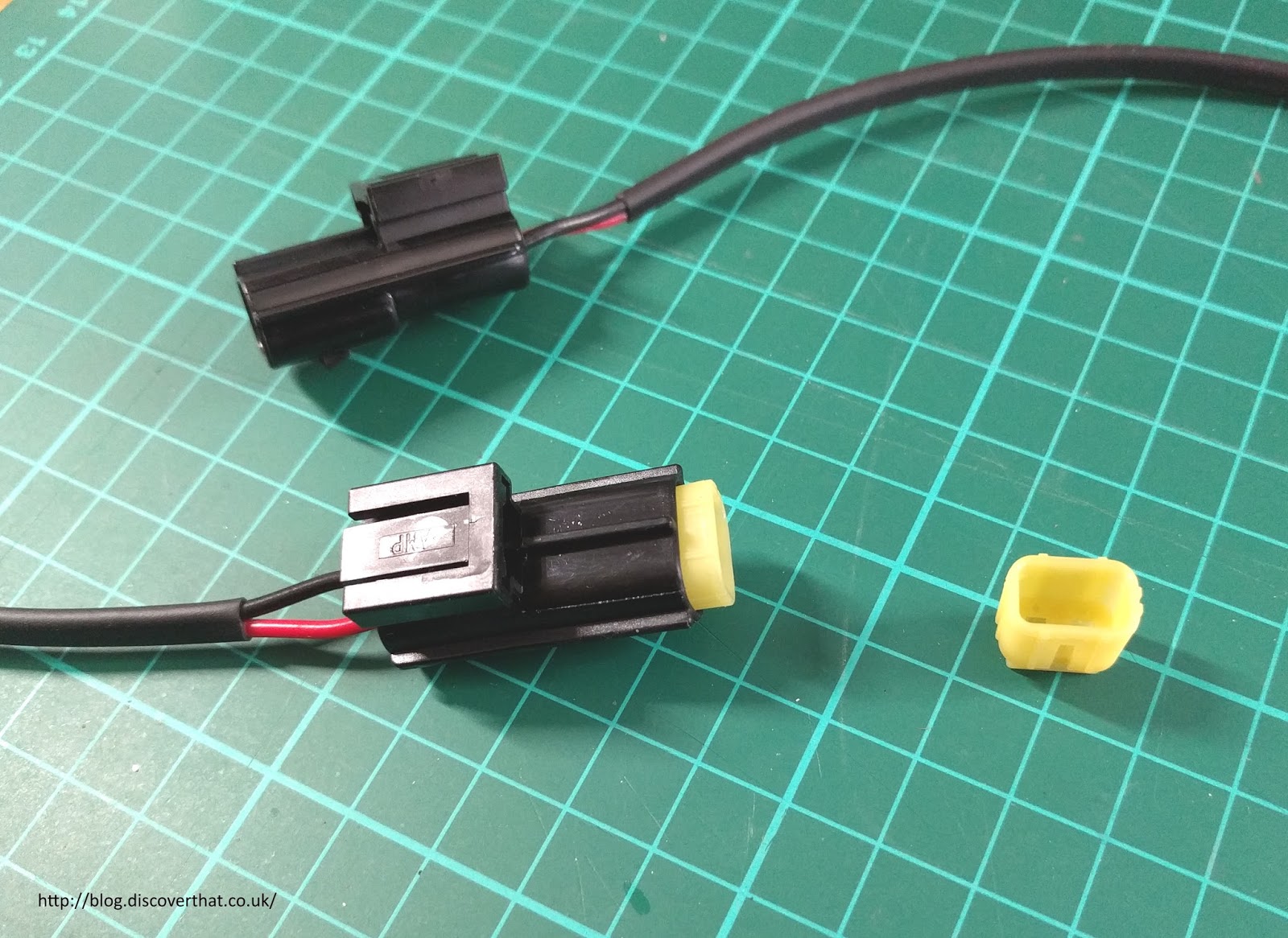
Instead of being connected permanently in to the main harness I have added Econoseal connectors, the same as used on the other indicator lights by Land Rover. To be consistent, I've deliberately wired them the same way round.


If all you want to do is fit an LED to the side repeater, the easiest thing to do is just plug in one of the 501 (W5W) LED replacements. You do have to be careful what size they are.

By trial and error I have found out that many of the W5W replacement LED bulbs are too long to fit the existing indicator repeater lenses. As I had several of these oversize LED lamps I've designed the holder to fit these. Any shorter LED W5Ws would obviously also fit.


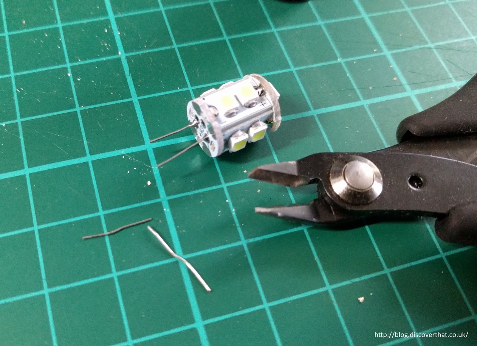
Typically the LED's are held in to their plug by simply having the wires bent over. This is similar to the original design of the glass W5W lamps. By unbending the wires the LED section comes out easily and can be slipped in to my 3D printed holder.


The wires on the cable are pushed through the holder and soldered on to the legs of the LED close to the base of the LED.


The holes for the wires in the prototype would only just fit a 1mm2 cable. I've adjusted the 3D model to have larger holes. It will probably still be a tight fit.


The harness is about 350mm long with 20mm exposed at the lamp end and 30mm exposed for the Econoseal connectors.


No more than 10mm of un-insulated leg should remain exposed. The wires are pulled back down so the solder joint is protected and insulated by the plastic holder.

It's important to get the wires the right way round because LED's have a polarity.


The ones I had were marked + and - but they are easily tested with a small 9V battery.


I added the Econoseal connectors and the rubber O ring.


I could have reused the old O rings but I happened to have a box of assorted and one was a good fit.

Left poor fit - Right better crimp results

Worth noting that if you work with the small pins, on things like the Econoseal connectors, a better quality crimp tool makes the job a lot easier.


Once in place the leads are held in to the holder and made water tight by filling the base with mastic. I've used black RTV silicone sealant. It would work equally well with potting resin if you have any to hand.


On the car the old holder is cropped off and the corresponding connector added to those leads.

I found it easier to work through the side light hole as the repeater wires just reached.


Reassemble the car and test all the lights.


Immediately afterwards Shelley took the car for a test drive :-)

==

Cura 3D printer settings

Downloads:
Side Repeater Blend file
Side Repeater STL file
Licence attribution

==