Search This Blog

Showing posts with label Nanocom. Show all posts

Sunday, 17 June 2018

Swapping the 10AS immobiliser

As mentioned in a previous post I wanted to maintain factory features and factory look and feel but add central door locking to our Defender, called Fender.


To this end I have swapped the Lucas 10AS immobiliser for one that has central door locking (CDL.) This is not easy because Land Rover, sensibly, fitted this is an very awkward to get to location behind the dash binnacle.

I have used a Discovery Lucas 10AS immobiliser, which has CDL, to replace the Defender variant, which does not. By doing that I keep the standard Land Rover style 2 button key fobs (plips) and I am able to enable the same immobiliser features exactly as factory fitted.

I used a Nanocom to setup the 10AS, as noted in a previous article.


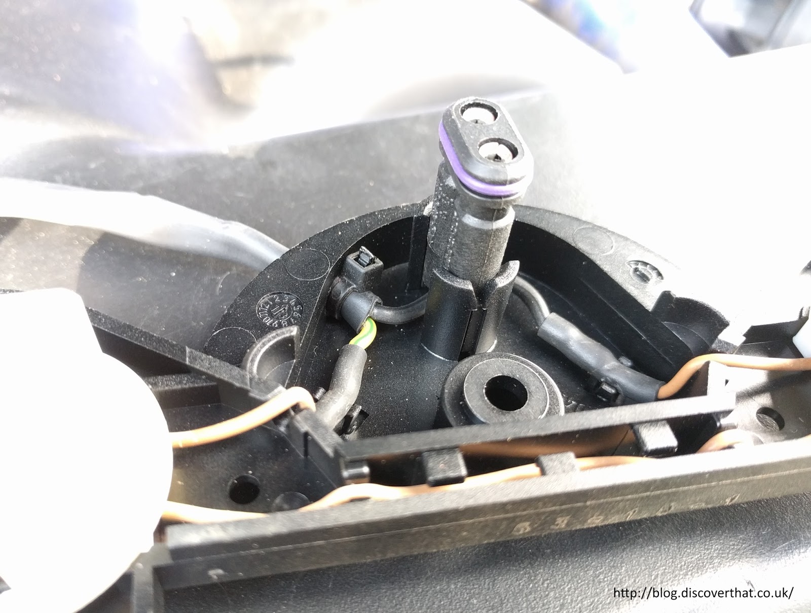
To get to the 10AS in Fender I removed the dash binnacle, disconnected the odometer cable and put the dash to one side. I'm not happy with it dangling supported by the wiring harness but I have been unable to find a better way to get it out of the way!


I also removed the small switch pod, which houses the hazard and fog light switches and the speaker below that. With all that removed I had visibility and access to pull the cables from the bottom of the 10AS.

The 10AS is bolted to the bulkhead above the steering column. There are green and grey connectors on the lower side. Each of those has a fairly easy to depress latch in the centre of the connector, facing the steering wheel. Pressing that in and pulling, with a bit of wiggle, and the connector comes out easily. The grey one is a little more difficult because it is immediately above the steering column but there is just enough gap to get the connector out and back in again.

Once disconnected I pulled both the connectors through the speaker hole.

To add CDL, I needed to connect two wires to the green connector and one wire to the grey connector.  Pins, 2 and 3 on the green connector and pin 7 on the grey connector. I bought the two different size pins from RS components.
I've already written a post detailing the connectors and pins I've used.


I wired up a short harness in the shed before starting work in the car. I decided it was easier to have a set of joints under the bonnet rather than trying to run the wires all the way to the doors in one long run. I used the wires from the Hawk CDL kit that I had bought off of e-bay. I maintained the Hawk colour coding for ease of installation. A blue and green wire, each with the larger pin to fit the green connector. A brown wire with the smaller pin to fit the middle of the grey connector.


To push the pins in to the existing connectors it is necessary to open up the connector housings. The green connector has 4 tiny plastic latches on the rear upper part of the housing. One latch at each end and another two either side of the main finger latch. A bit of poking with a screwdriver and some force got that upper part open.


The grey connector is easier, it just has two plastic latches, one either end.

Making sure the pins were the right way up, they just push in until you can hear the click of the plastic internal lock engaging with the pin. A small screwdriver sometimes helps if the wire is a tight fit.


Once I was sure the wires were in the right place I reassembled the connectors and taped the new wires to the outside of the existing cable bundles.

At this point I plugged in the replacement 10AS and attached a door solenoid, temporarily to the cables while I tested. I locked and unlocked the car, with the solenoid following as it should and I started the engine. This do not all work first time. I don't know why but it took a couple of locks and unlocks with each plip until the hazard lights followed as I had configured. It was unexpected but without making further changes, the reactions from the car settled down to what I had intended.

I removed the temporary setup before continuing.

Now for the tricky bit. Getting the previous 10AS out and the desired one in its place!

With a long number 2 pozidrive screwdriver one of the two bolts can be reached easily through the hazard switch hole.


The tricky bolt is to the left of the module. Everything is in the way. I managed to make up an extended 1/4" socket contraption with a PZ#2 bit on the end, that just reached and had enough movement to undo the bolt. Luckily neither bolt was very tight.

With the bolts removed the module can be slid to the right and removed through the speaker hole.

My replacement module had broken mounting tabs so I had the extra task of opening up the module, swapping over the internals and putting the replacement lid on the lower section of the original case. That way I got the correct stickers on the module but now with intact mounting wings. I'll be back to those in a moment.


The module goes back in the same way the old one came out. The wiring harnesses need to be pulled out the way and it took a bit of fiddling to get the unit back in place without trapping any cables. The good thing is that those cables conveniently hold the module roughly in place.

Despite the module being held up by the cables, I struggled to get the left hand bolt in to the hole with the limited space that is there.


My solution was to cut the left hand mounting hole in to an open slot and put the bolt with washer in the car first. That worked very well and made the job a whole lot easier. The right hand bolt is easy to fit and needs no such modification.

I deliberately did not over tighten the bolts.


I then ran the short harness through the bulkhead and temporarily secured along the back of the bulkhead under the bonnet.


I plugged all the connectors back in but before putting the dash back together I did a further test with a temporary solenoid hooked up. At this point, while I remembered, I swapped the remote key fobs on each set of keys and put the previous ones with the previous 10AS.

All back together, remembering to connect the odometer at the appropriate point in the reassembly.

More test engine starts, with the immobiliser activated and deactivated to ensure that everything is working as it should. The last job was to put the battery on charge to top it up after all the cranking without any movement.


Now I am ready to move on to the next stage of fitting the central door locking.

==

Related articles:
https://blog.discoverthat.co.uk/2017/04/lucas-10as-connectors.html
https://blog.discoverthat.co.uk/2018/06/central-locking-poc.html
https://blog.discoverthat.co.uk/2018/07/fitting-defender-central-door-locking.html

==

Sunday, 3 June 2018

Central locking PoC

In one of my mad scientist moments I have rigged up a test board for the central locking set-up I want to install in Fender. Specifically I wanted to keep standard Land Rover style (c.1998) key fobs but add central door locking.


This is the proof of concept (PoC) that I can configure a Discovery 1 Lucas 10AS immobiliser to work a third party set of door solenoids that I can fit in to our Defender. Land Rover models between 1995 and 1998, and a few years either side, used the Lucas 10AS immobiliser but with varying features enabled. The Discovery variants included central locking.


Among other things, as part of the PoC, I needed to be able to set-up a remote control key fob (blip) with the Nanocom. I've bought the add-on licence that allows me to have some of the Defender systems on my, otherwise, Discovery 2 (TD5) licensed Nanocom diagnostic tool.


The outcome is that everything I wanted to test, worked.


I now know which wires to connect and which way round to connect them.

==

Configuring a 10AS with a Nanocom


The 10AS is on the Defender TD5 menu.


Before you start, always save the existing settings to an SD-Card.
You can open them to get back to, what is hopefully, a working state.


Key fob (plip) learning
This is on the Utilities menu
Plip Learn
While the dialogue is on the screen press the plip buttons until the hazards flash or, if like me you are working on the bench, you hear the relay trip.
All plips that you want to work have to be done at the same time because you cannot control which of the 4 plip stores will be used so you may or may not overwrite the existing plips.
Just do one plip after the other.
When all are done, press the OK button on the Nanocom.
The plips will work immediately however I prefer to test with the Nanocom disconnected, just to be sure it has completed correctly.

Passive Immobilise
This caused me a lot of grief. There is a gotcha with this setting. If you enable this when disconnected from the car, the plips will no longer work!


It took me hours to find this out. I reverted all the settings and they worked, so I eventually set them one at a time until I found the one that caused it to stop working!
I assume this is a security feature. I would guess that if the passive immobiliser coil is removed the 10AS goes in to immobilise mode and stays there.
When I get it in the car I'll be able to test this theory.
[23 June 2018: I have confirmed that with a Passive Immobiliser Coil attached, the setting to use it can be enabled and the key fobs work as intended.]

The Passive Immobiliser requires the correct type of plip
I believe it is the Freelander versions that do not have the parts included on the circuit for use with the passive immobiliser coil.
You can't tell from the outside of the key fob.
If you have the unsupported type you could disable the passive immobiliser in the 10AS until you get the right internals for the plip.

This is taken from a forum post:
"Not all 17TN keyfobs are the same.
YWX101220 which is the correct part number for a defender has a built in immobilser chip as well as the radio transmitter.
YWX101200 is a freelander 2001 on keyfob which hasn't got the immobiliser chip. "
http://www.defender2.net/forum/topic5063.html

All the key fobs I have purchased from e-bay, that claim to work with a Defender, have worked correctly with the passive immobiliser.

Defender and Discovery 10AS
I was unable to change the setting for the name of the vehicle. I was testing with a 10AS from a Discovery 1 and although the Nanocom would allow me to make the change to show Defender, when the settings were written to the 10AS, the vehicle setting reverted to Discovery 1.

Using the Discovery 10AS in the Defender, the engine management warning light is permanently illuminated. All the functions work, that I have needed. I've checked the circuit diagram and the only thing that connected to that indicator is the 10AS.
My guess is that, because I can't change the type setting, to indicate that it is a Defender, the 10AS is looking for equipment that is not attached. As far as I can tell, it does not affect the functionality required in a Defender.

According to the handbook, the engine management warning light is supposed to flash if an attempt is made to start the engine while it is immobilised. I have never noticed it do that and more often the hazards will be flashing as the alarm will have been activated. Therefore, I am happy not to have that feature in exchange for being able to add central locking.

Alarm Coding Data
When you go to write the settings you get a second dialogue that asks if you want to save the Alarm Coding Data and warns that this is for the advanced. I now press 'No' on that screen, so only the normal settings are changed and not the advanced data.
I am using educated guesses, so I do not qualify as 'advanced'. 'Dangerous amateur' would be a better description. I have tinkered with the alarm coding data but with unsatisfactory results.
I decided, as it was working, I would leave well alone, even though the entries looked odd.

==

Related articles:
https://blog.discoverthat.co.uk/2017/04/lucas-10as-connectors.html
https://blog.discoverthat.co.uk/2018/06/swapping-10as-immobiliser.html

External Links:
https://www.nanocom-diagnostics.com/downloads/download/lucas-10as-alarm-nanocom-evolution
https://www.nanocom-diagnostics.com
I use the lower cost Nanocom but the same company do a professional grade product that can be licensed for just one system, one of the options is the Lucas 10AS:
https://blackbox-solutions.com/shop/category/faultmate-msv-2
https://blackbox-solutions.com/shop/product/sm031

==

Sunday, 20 August 2017

Height sensor replacement

For a few days the rear air suspension has been troublesome. It would slowly drop down on its haunches instead of rising up when starting the car.


A few restarts and tinkering with the calibration using a Nanocom would sort it out but it was a bit inconvenient.

I was hoping it would last until the weekend but by Thursday it was obvious that was not to be, so I took the day off on Friday to fix it.


I was reasonable confident that it just needed new height sensors. I'd had a couple in stock for years from a previous problem that only needed calibration to fix.


I took the opportunity to replace the broken connector housing on one side and to seal the unused cable holes in the connectors, just to be sure.


I think the main cause of the problem was not so much a faulty sensor but a corroded aluminium bush that was fused solid on to a steel bolt on the drivers side.


It was supposed to freely rotate as the suspension arm moved but that was not happening. I had to grind it and bash it with a chisel to get the bush off!


A few cups of tea later and its all back together.


Just needed to be calibrated using the Nanocom. I set the height at 47cm from the apex of the wheel arch to the centre of the wheel.

After a test drive and a couple of journeys, including a trip to have an 'all day breakfast', it is still riding as expected.

Sunday, 26 February 2017

Discovery 2 ABS repair

I have been getting some intermittent faults with the ABS system. Three of the dash lights illuminate to indicate this. Known as the three amigos this is the ABS, traction control and hill decent warning lights all at the same time.


That light combination means there is an error but not what the fault is. I plugged in the Nanocom to find out.


An electrical fault with the ABS shuttle valve. It did not take long on the Internet to find out that this is a common problem. It can be rectified by replacing the ABS shuttle valve modulator switch assembly (SWO500030). That's a relatively low cost part. Luckily it is also a fairly easy part to replace.

It is even possible without draining the brake fluid, as seen in the linked video. As it didn't need messing with any critical systems it made it a job I was confident at doing.

There are several references on various forums about how the problem is likely to be the internal connector within the block and may re-occur. There is a suggested longer term repair for the ABS modulator switch by extending the wires outside the plastic bit of the switch case to bypass the internal connector.

To save myself a bit of time, I bought a kit where the wires had been extended for me and a connector added.


There is nothing really wrong with the idea of the kit I bought. It is a good choice of connector, an Econoseal, to match other Land Rover connectors and from the same range as the multi-pin connector on the Wabco ABS unit.

The kit is designed so that there is no need to cut any wires nor crimp any pins. Instead two existing leads need to be extracted from the multi-pin plug and re-used in a two pin Econoseal connector. The kit comes with a good set of instruction about how to do that. For those that are not confident with car electrics, this is a good kit.

The bit I am not keen on is that the end result would be that the ABS unit is attached directly in to the wiring loom. In my opinion this could be a nuisance for maintenance in the future should there be a more significant problem with the ABS valve block!

I made a slight variation and cropped off the supplied black wire and spliced it on to the black with grey stripe (pin 8) from the harness.


I taped it up securely as I also did with the now redundant loose end on the modulator switch lead.


The end result is that I only need the two pin connector on the modulator section and the whole ABS block can be more easily removed from the car without reversing the kit wiring installation.


That change meant I only had to remove one wire, the yellow with green stripe (pin 9), from the multi-pin connector.

With the electrics all prepped the next job is to get access to the bit that needs replacing under the ABS block.

The three allen bolts under the Wabco unit can be reached if it is lifted out of its mountings. First unclip the brake pipes from the edge of the bulkhead.


Taking off the upper clip from the three pipes routed together, makes it easier to maneuver the block to a workable position.


The block has two 10mm nuts at the back that need to come off however the one at the front only needs to be loosened because it is in a slot. Pulling it up at the front gives enough room to remove the metal cup from the rubber mounting then the whole unit can be pulled forwards to clear the rear bolts from their fixing holes.


You need a 4mm allen key to remove the three bolts to free the valve modulator switch unit. They are very stiff because they have thread lock on. My tiny ratchet made the job a lot quicker.


The old assembly pulls downwards to remove. The connector remained in the block and had to be grabbed separately to get that out.


The new one goes in easily and the supplied new allen bolts go back in. They have fresh thread lock on them.


The block can be bolted back on to the car. The brake pipes can be clipped back on to the bulkhead. The next job is to finish off the electrical connections.


One pin has to be backed out from the multi-pin connector. This is fairly easy with a small watchmakers size screwdriver. Once the yellow shield has been removed you can get the screwdriver in to hold the plastic latch out of the way. The wire pulls out the back.

One comment about the kit I bought. The person who crimped the pin on was not fully familiar with Econoseal connectors. To be fair, it took me a while to find the correct instructions.

Upper seal, wrong, lower seal (original) correct
The crimp for the insulation should go over the rubber seal so that when you push it in, to the plug housing, the seal is pushed in at the same time. It is awkward trying to use a screwdriver to shove it in afterwards when not attached to the cable.

In my opinion, they also used the wrong sized seal for the gauge of wire. I would have used a yellow or brown colour seal which has a larger diameter inner hole.


A little tip. The blanking seal that needs to go in the now vacated pin 9 position, will only go in one way round. As shown in the above photo. Hold the smaller end and push the larger in end.


Assemble the new 2 pin socket and connect it up.


Back inside the car to connect up the Nanocom again.


Clear the faults.


I took it for a short test drive and on return there were no faults.

==
Update: 12 March

It's been two weeks and no sign of any faults.