Search This Blog

Showing posts with label Defender. Show all posts

Wednesday, 23 August 2023

Defender hazard and indicator light diagnostics

Defender 1984 to 2016

Hazard and Indicator Lights Diagnostics

“Many problems with the indicators are actually faults with the hazard switch.”


Wiring Differences

The various models of Land Rover Defenders from 1984 through to 2016 have similar wiring but have slightly different colour wires connected at the hazard switch.

The wiring colours are written as the main colour first with the stripe colour after. As an example, a light green wire with a white stripe would be written as Light Green/White (LGW). A grey (slate) wire with a brown stripe would be written as Slate/Brown (SN).


After 1998, the colour of the ignition feed changes to White/Green and the permanent feed to Purple/Brown.

Operation

To better understand the significant functions, only the indicator operation is described in the following. The panel lighting and tell-tale light functions are not noted here:

When off (not depressed)


Indicators can be used.


+12V to the flasher relay is supplied from the ignition feed.

The ignition has to be in position two for the indicators to work from the column controls.

==

+12V ignition, Dark Green or White/Green, depending on the model year, is connected to the Light Green wire to the flasher unit.


When on (depressed)


Hazard lights in use.


+12V permanent feed is connected to the flasher unit.

The return from the flasher is connected to both the left-hand and right-hand side indicators.

Both sides indicators will flash.

==

Permanent +12V Purple or Purple/Brown wire is connected to the Light Green wire to the flasher unit.

The Light Green/Brown return wire from the flasher unit is connected to both the Green/Red and Green/White feeds to the indicator lamps.


Diagnostics

I like to make up a test wire using an inline fuse. This is to avoid mistakes accidentally shorting out a live to earth. A 5A fuse is suggested. It needs to be less than 10Amp to avoid the fuse box fuse blowing first.

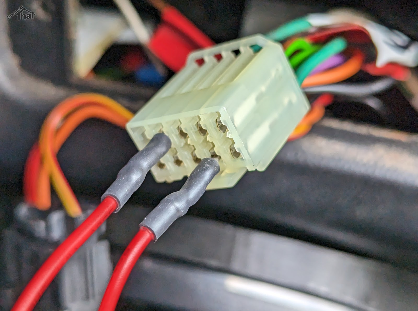
Most indicator faults can be diagnosed via the hazard switch connector.

To Test

Method

Expected Result

Indicator wiring


At the hazard switch connector.

Connect the permanent live, Purple or Purple/Brown, to the Left and Right indicator wires, in turn.

Left is Green/Red

Right is Green/White


The indicators on one side would illuminate. Not flashing.


Flasher unit and indicator controls


At the hazard switch connector.

Connect the permanent live, Purple or Purple/Brown, to the Light Green flasher feed.


Operate the indicator stalk switches.


The appropriate indicators should flash.


Ignition live feed


At the hazard switch connector.

Repeat the above two operations using the ignition feed Green or White/Green wire, in place of the Purple wire.

The ignition switch must be in position two.


Same results as above.

Indicator stalk switches


At the indicator stalk pins.

Bridge the Light Green/Brown common wire from the flasher to the indicator wires, in turn:

Left is Green/Red

Right is Green/White


The appropriate indicators should flash.


Just in-case anyone notices. The photos are from a 1998 300TDi re-wired to use the switches from a newer 2002 onwards TDCi.

Troubleshooting

Bridging any of the wires at the connector works but using the switch fails.


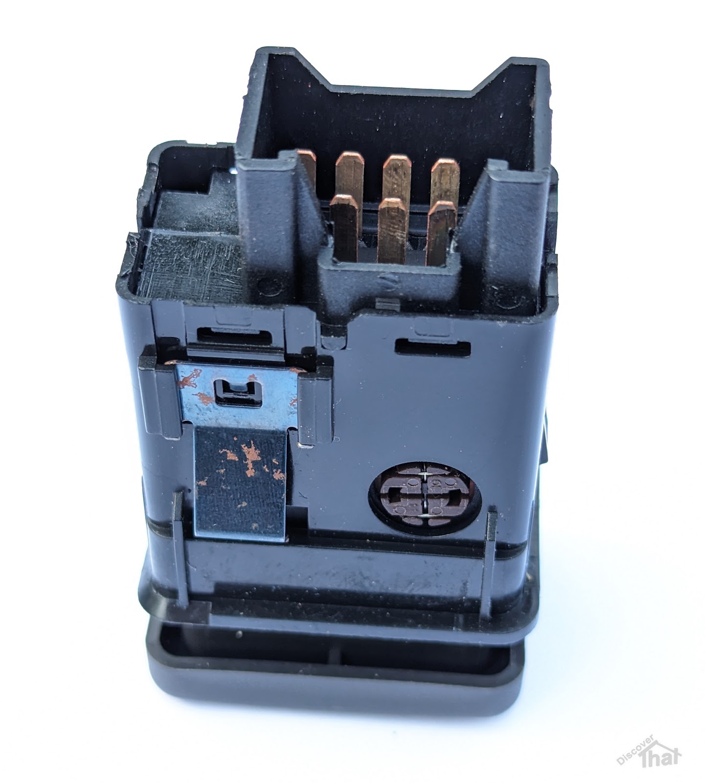
Clean the connector pins on both the connector and out the back of the switch.


If the above fails to resolve the issue, it will be necessary to replace the switch.


Either bridging of the permanent or ignition wire tests fail.


Check the appropriate fuse.


The indicator lamps illuminate when connected to a live but do not work through the flasher unit.


Remove the flasher unit from its socket and clean the pins.


If the above fails to resolve the issue, it will be necessary to replace the flasher unit.


Cleaning Connector Pins

This can be done with a pencil rubber or more commonly with fine sandpaper. A needle file can be useful to get into confined spaces.

Where the electrical interface is inaccessible, a chemical contact cleaner can be used, however this often also needs the connector to be inserted and removed a few times to assist the cleaning process.

If the connector pins do not hold tightly, small, pointed nose pliers can sometimes be used to gently close up the female portion of the connector pins.


Fuses

Ignoring the main fuses and links because there would be other symptoms if they had blown.

Up to 1998

300TDi


Permanent Feed, Purple – Central interior fuse box Fuse 1 (15A)

Ignition lighting feed, Green – Central interior fuse box Fuse 3 (15A)


1999 to 2001

Early TD5


Permanent Feed, Purple/Brown – Central interior fuse box Fuse 31 (15A)

Ignition lighting feed, White/Green – Central interior fuse box Fuse 21 (10A)


2002 to 2016

Late TD5
TDCi Puma


Permanent Feed, Purple/Brown – Central interior fuse box Fuse 31 (15A)

Ignition lighting feed, White/Green – Central interior fuse box Fuse 21 (10A)


Switch Types

Defender

1983 to 2001

TD, 200TDi, 300TDi and early TD5

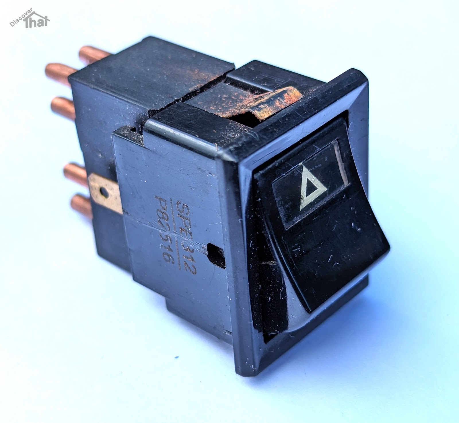
YUF101490 Lucas switch


Defender

2002 to 2016

Late TD5 and TDCi Puma

YUG000180LNF


Freelander

1996 to 2002

YUG102220


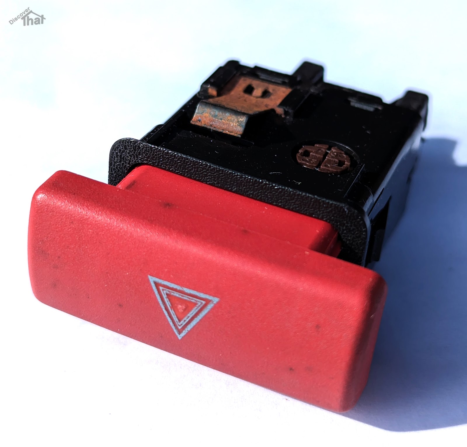
The early Freelander hazard switch body is the same as the late Defender. It uses the same wiring and connector but the key cap is different.


In the event that a Defender hazard switch is not available, that era Freelander switch can be used as an alternative. In order to make it fit the dash panel, the key cap needs to be carefully removed and swapped over with the Defender key cap. It is held on by two plastic clips, one top and one bottom.


I'll add to this if I discover any more tips.

I only have direct experience of a 1998 300TDi and a 2009 TDCi. All other information is taken from manuals and third-hand information. There are likely to be exceptions and some cars, like my own, will have been modified.


==


Thursday, 3 March 2022

Defender 300TDi heated seats

This is the second time I've added heated seats to Fender. This time I've done what I think is a tidier job.

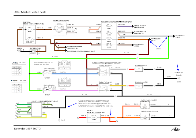
Fender is a 1998, 300TDi, so there was no factory fit heated seats option. As usual, I've had to work out my own wiring. There is a convenient feed for air conditioning, which I've used for the heated seats.


It's not very many week ago that I fitted the heated seat wiring to our TDCi Defender, Thunder Truck


As then, I've fitted relays. Land Rover wire their heated seats directly via the switches. I am unsure of the rating of the switches and the after-market heated seat pads do not state what current each circuit requires. All I know for sure is that they are fitted with a 20A fuse, so it is safe to assume each seat uses no more than 10A. I've used that to size all the wire gauges.


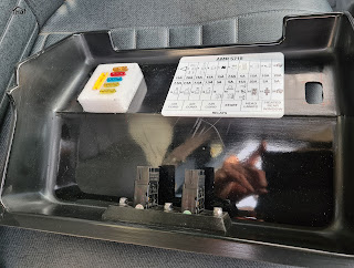
I'm using an extended fuse box cover. I bought it so I had enough space for the extra relays without struggling but it was also the ideal place to mount the heated seat switches.


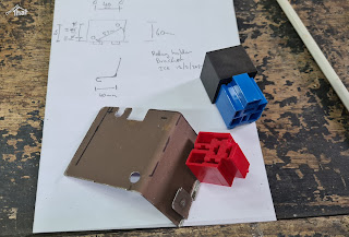
I made a bracket to mount the relays under the existing fuses.


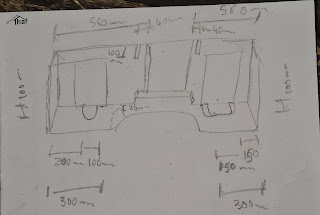
Measuring where to cut the rubber mat

Before fitting the new Exmoor Trim seats I fitted the under seat rubber mat. Another Exmoor Trim product.


I've used some 1/2" (12.7mm) spacers to stop the seat rails catching on the thick rubber mats. The mats are so thick, I've found, that it needs at least 12mm spacers for the seat to move freely.


I needed longer seat bolts, so I bought some stainless steel M8x40mm torx pan head bolts which do the job nicely. I've done the same in both Defenders.


With the mats and the seats in, I threaded the cables before fitting the carpet and cubby box.


I've used Discovery 2 (D2) heated seat switches because, at the time I was looking, I could not get Defender TD5 or TDCi switches. The D2 switches are the same as the Defender switches, they just have different style caps. I've wired them so that the tell-tale lamps and the backlights work.


Tested and working well. Nice and warm.

==

Sunday, 20 February 2022

Wheel carrier modification

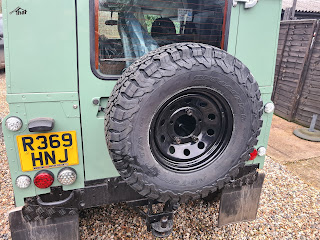
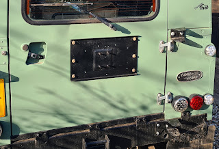
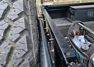
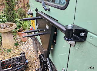
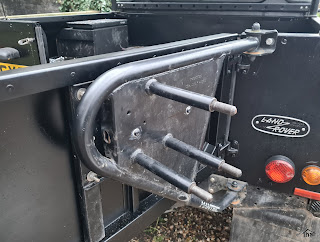
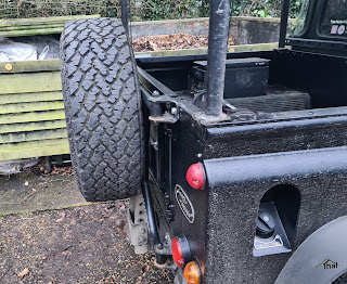
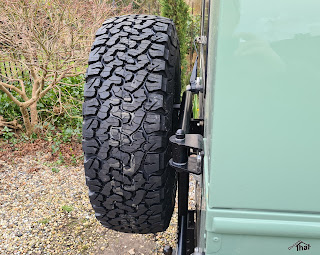
I've had a Mantec swing away wheel carrier, fitted to a Land Rover Defender, for several years. A similar design is now sold by Britpart. The Mantec wheel carrier has worked well. It's a nice robust structure and opens with the door.


To allow it to swing with the rear tail door, the original design uses a large plastic plunger. This works well to allow the wheel carrier to move with the door but has the disadvantage that unless it is exactly aligned, the carrier will lift the door off its hinges. This happened to ours when it was moved to another Land Rover.


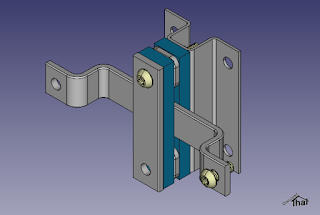
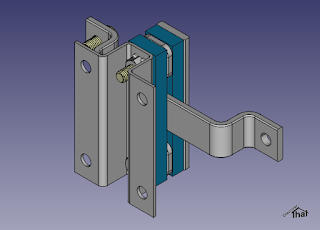
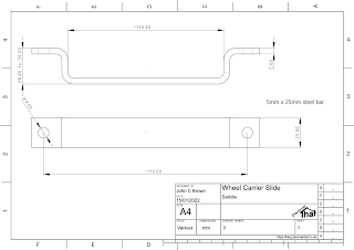
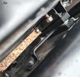
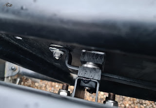
That got me thinking and I came up with a design that slides in both directions, so the door position is not influenced by the carrier at all.


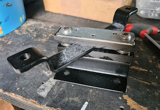
A friend made up a couple of jigs from my designs and pressed the more difficult parts in his workshop. 


I put them together in my shed. I cut the two plastic sliders from some 10mm thick nylon like material I had bought many years ago for another project.


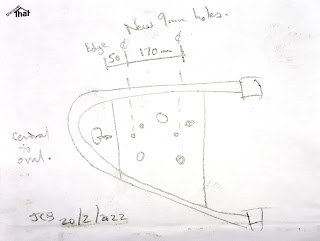
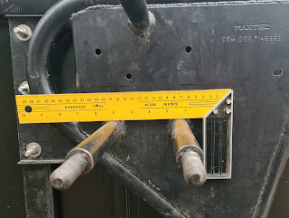
The carrier needs two 9mm holes drilled. These need to be along the same centre line that the original plunger fitted. This is easy to find by looking at the oval hole in the end plate, where the plunger used to bolt through.


There is little room between the door and the carrier. 


It took a little experimenting to work out the easiest way to get the nuts on in that confined space. For me, the best method was to loosely attach the larger strap to the carrier first and then put the nuts on the door side.


I've fitted it to two cars and, so far, it's worked very well.


The carrier does not need any alignment when fitting so everything can be bolted up tight, as you go.


==
(C) Copyright 2022, John C Brown.

Please ask permission before using this design.

==

Sunday, 23 January 2022

Defender interior lamp connector

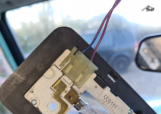
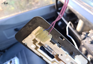
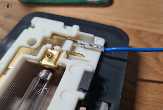
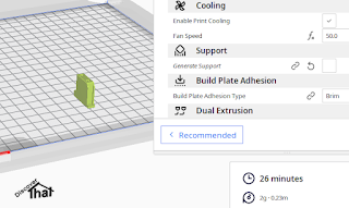
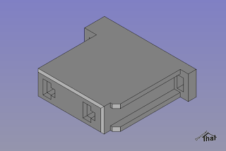
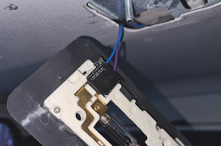
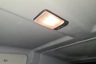
In the process of fitting the rear headlining and specifically a lamp in the rear, I could not find anywhere to get the connector that fits the standard Defender light fitting. They have, in the past, been available on ebay, but not when I was looking. My solution, as usual, was to design and 3D print one.

Original Part

I believe that the connector is part number AMR3158.

Factory fitted connector


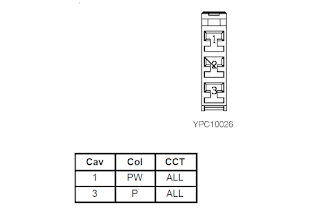
It is connector C357 in the 1997 electrical circuit diagram.


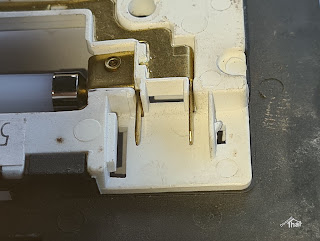
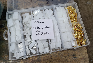
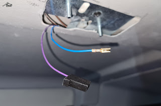
Luckily, the spades fit perfectly into the commonly available 2.8mm connector pins. The 2.8mm connector housings that are readily available online, have narrower spacing between the pins.

Readily available 2.8mm connectors


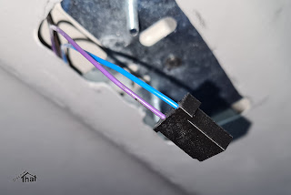
I designed a housing with spacing to fit the lamp, using the 2.8mm pins that I already had. The light only uses two pins 10mm apart.

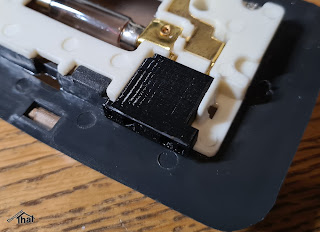
Just off the printer

Snug fit

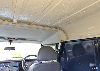
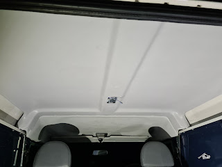
The bare roof and condensation

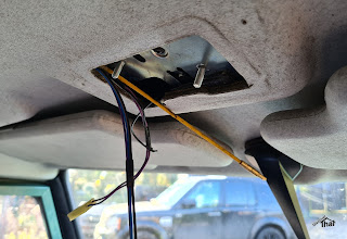
Threading to the front light

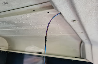
Pulled cables through to the rear

I threaded the cables above the front headlining prior to fitting the rear.

Honestly, it does fit... 

... just about. Needs manoeuvering


This was intended to be an article about the lamp connector but I'll mention fitting the headlining, while I'm here.

The headlining that I fitted was purchased from Simmonites. It's a thin fibreglass panel.

There are a number of trim clips holding up the headlining. I measured the one central trim clip from the centre of the row of trim clips between the front and rear sections. That avoids the risk of movement while measuring. I then marked the row of trim clip holes by offering up the two halves and visually looking at the centres. They were 15mm from the edge and I drilled 8mm holes.


I cut the hole for the lamp holder using a rotary tool and drilled a small hole in the centre spar to secure the bracket.


There are three wires, spliced in to the same cables from the front light.

The purple wire is a permanent live. I had purple 0.5mm2 cable available, so it matches the original. The correct method is to disconnect the battery but, of course, I just took care not to touch anything while fitting the crimp. I was happy when the end of the purple cable was safe in the housing.

I had blue 0.5mm2 cable available, so I connected that to the purple/blue cable of the original lamp. It's an earth via the immobiliser ECU. 

There is also a black earth cable, using a 6.3mm spade connector, plugged into a tag cut into the bracket. The bolts are the earth for the lamp.


The connector was a tight fit but worked.


Download:

Connector C357 AMR3158 STEP and STL (Zip)


==