Defender 1984 to 2016
Hazard and Indicator Lights Diagnostics
“Many problems with the indicators are actually faults with
the hazard switch.”
Wiring Differences
The various models of Land Rover Defenders from 1984 through
to 2016 have similar wiring but have slightly different colour wires
connected at the hazard switch.
The wiring colours are written as the main colour first with the stripe colour after. As an example, a light green wire with a white stripe would be written as Light Green/White (LGW). A grey (slate) wire with a brown stripe would be written as Slate/Brown (SN).

After 1998, the colour of the ignition feed changes to White/Green and the permanent feed to Purple/Brown.
Operation
To better understand the significant functions, only the indicator operation is described in the following. The panel
lighting and tell-tale light functions are not noted here:
|
When off (not
depressed) Indicators
can be used. |
+12V to the
flasher relay is supplied from the ignition feed. The ignition
has to be in position two for the indicators to work from the column
controls. == +12V ignition,
Dark Green or White/Green, depending on the model year, is connected to the Light
Green wire to the flasher unit. |
|
When on
(depressed) Hazard
lights in use. |
+12V
permanent feed is connected to the flasher unit. The return
from the flasher is connected to both the left-hand and right-hand side
indicators. Both sides
indicators will flash. == Permanent
+12V Purple or Purple/Brown wire is connected to the Light Green wire to the
flasher unit. The Light Green/Brown return wire from the flasher unit is connected to both the Green/Red and Green/White feeds to the indicator lamps. |
Diagnostics
I like to make up a test wire using an inline fuse. This is to avoid
mistakes accidentally shorting out a live to earth. A 5A fuse is suggested. It
needs to be less than 10Amp to avoid the fuse box fuse blowing first.

Most indicator faults can be diagnosed via the hazard switch
connector.
|
To Test |
Method |
Expected
Result |
|
Indicator wiring |
At the hazard
switch connector. Connect the
permanent live, Purple or Purple/Brown, to the Left and Right indicator
wires, in turn. Left is
Green/Red Right is
Green/White |
The
indicators on one side would illuminate. Not flashing. |
|
Flasher unit and
indicator controls |
At the hazard
switch connector. Connect the
permanent live, Purple or Purple/Brown, to the Light Green flasher feed. Operate the
indicator stalk switches. |
The appropriate
indicators should flash. |
|
Ignition
live feed |
At the hazard
switch connector. Repeat the
above two operations using the ignition feed Green or White/Green wire, in place of the Purple wire. The ignition switch must be in position two. |
Same results
as above. |
|
Indicator
stalk switches |
At the
indicator stalk pins. Bridge the Light
Green/Brown common wire from the flasher to the indicator wires, in turn: Left is
Green/Red Right is
Green/White |
The
appropriate indicators should flash. |

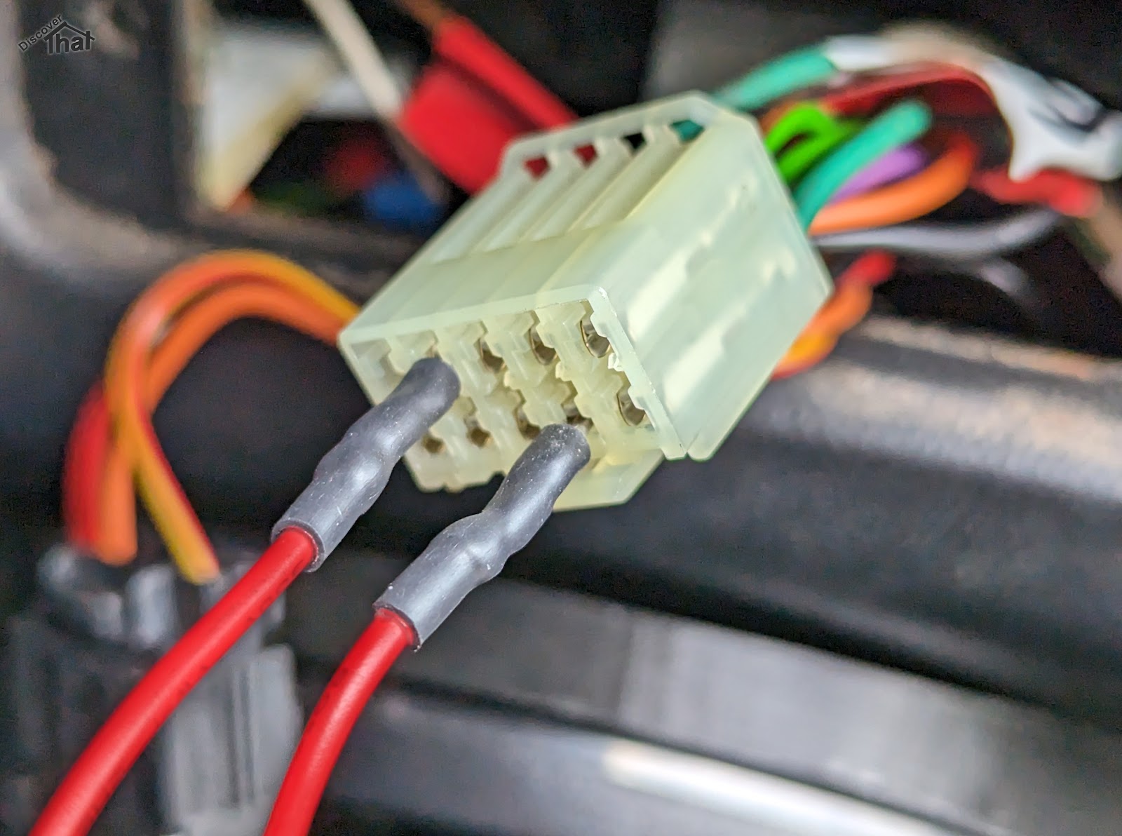
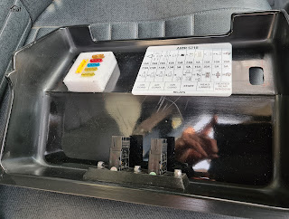
Just in-case anyone notices. The photos are from a 1998 300TDi re-wired to use the switches from a newer 2002 onwards TDCi.
Troubleshooting
|
Bridging any of the wires at the connector works but using the switch fails. |
Clean the
connector pins on both the connector and out the back of the switch. If the above
fails to resolve the issue, it will be necessary to replace the switch. |
|
Either
bridging of the permanent or ignition wire tests fail. |
Check the
appropriate fuse. |
|
The indicator
lamps illuminate when connected to a live but do not work through the flasher
unit. |
Remove the
flasher unit from its socket and clean the pins. If the above
fails to resolve the issue, it will be necessary to replace the flasher unit. |
Cleaning Connector Pins
This can be done with a pencil rubber or more commonly with
fine sandpaper. A needle file can be useful to get into confined spaces.
Where the electrical interface is inaccessible, a chemical
contact cleaner can be used, however this often also needs the connector to be
inserted and removed a few times to assist the cleaning process.
If the connector pins do not hold tightly, small, pointed
nose pliers can sometimes be used to gently close up the female portion of the
connector pins.
Fuses
Ignoring the main fuses and links because there would be
other symptoms if they had blown.
|
Up to 1998 300TDi |
Permanent
Feed, Purple – Central interior fuse box Fuse 1 (15A) Ignition
lighting feed, Green – Central interior fuse box Fuse 3 (15A) |
|
1999 to 2001 Early TD5 |
Permanent
Feed, Purple/Brown – Central interior fuse box Fuse 31 (15A) Ignition
lighting feed, White/Green – Central interior fuse box Fuse 21 (10A) |
|
2002 to 2016 Late TD5 |
Permanent
Feed, Purple/Brown – Central interior fuse box Fuse 31 (15A) Ignition
lighting feed, White/Green – Central interior fuse box Fuse 21 (10A) |
Switch Types
|
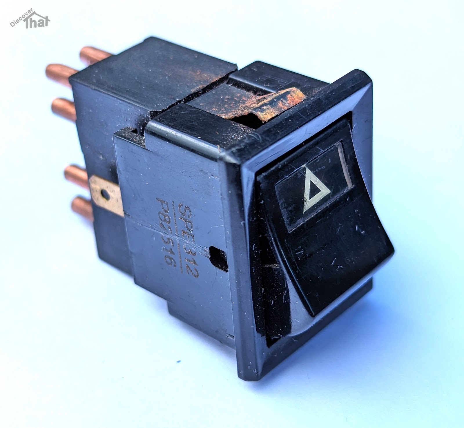
Defender 1983 to 2001 TD, 200TDi, 300TDi and early TD5 YUF101490
Lucas switch |
  |
|
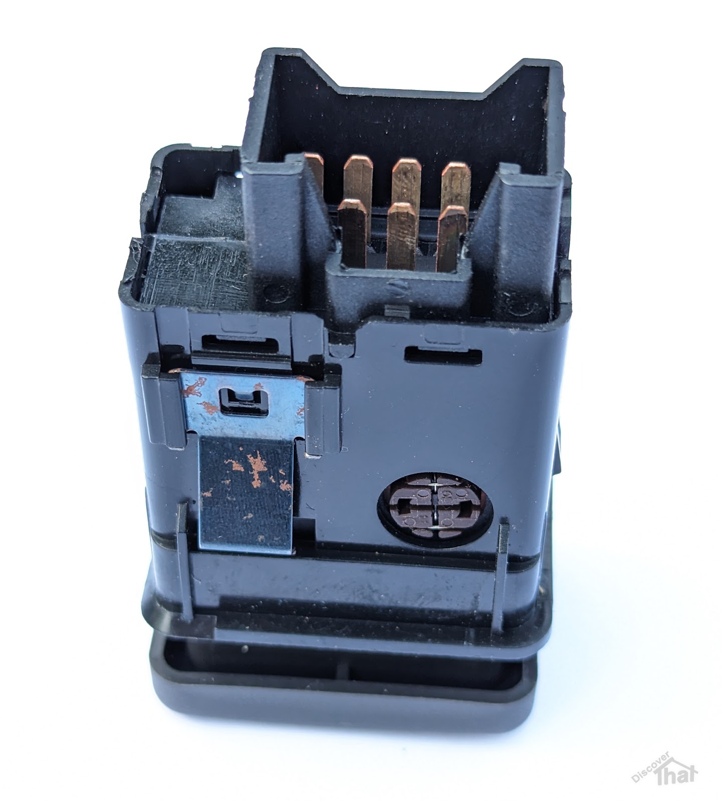
Defender 2002 to 2016 Late TD5 and TDCi Puma YUG000180LNF |
  |
|
Freelander 1996 to 2002 YUG102220 |
The early Freelander hazard switch body is the same as the late Defender. It uses the same wiring and connector but the key cap is different.  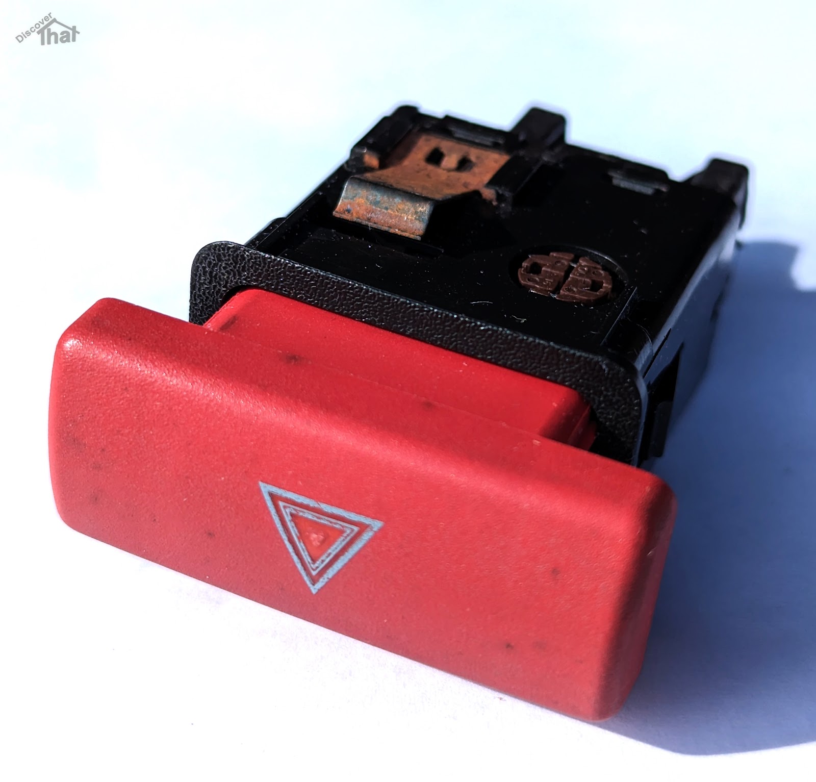 In the event that a Defender hazard switch is not available, that era Freelander switch can be used as an alternative. In order to make it fit the dash panel, the key cap needs to be carefully removed and swapped over with the Defender key cap. It is held on by two plastic clips, one top and one bottom. 
|
I'll add to this if I discover any more tips.
I only have direct experience of a 1998 300TDi and a 2009 TDCi. All other information is taken from manuals and third-hand information. There are likely to be exceptions and some cars, like my own, will have been modified.
==