The doors on Fender are, to say the least, a bit rusty.
Some time ago I purchased a pair of new doors and had them sprayed black ready for the full respray in the future.
This weekend I fitted the first of them.
Not a particularly difficult job but it took a while as this is the first time I've done it. There's no point in going in to detail but I will mention a couple of things that may or may not help anyone else doing this job.
The first thing I did was to check that the door hinge bolts were free. I sprayed them with penetrating oil but luckily all of them on Fender came out easily.
With the door removed I took the opportunity to paint under the hinges with black which will be the final colour of the rest of the car.
To save repeating it at every stage in this post, I used a lot of White Lithium Grease. I sprayed it on every, screw, bolt and hole. This is primarily to reduce corrosion but, in the case of bolts, to help to keep them free to remove in the future.
I bought a kit of all the parts to replace the window runners which includes the plastic filler pieces which go on the outward side of the window channel.
The felt lined window runners fit inside the lower part of the plastic filler strips.
The runners are held in by small screws. I did watch a video where they used small dabs of adhesive instead of screws but I decided I liked the screws better. Easy enough to drill a 2mm hole and fit the self tappers. I only used 2 on each runner at the top and one on each of the long runners where they touched the frame at the lower end.
The kit with the runners included aluminium strips that fit behind the window runners. I have no idea what they are for but I fitted them anyway.
The top bracket on the hinge side is held on by a single bolt and needs to be transferred to the new door.
As I had the doors apart I fitted a new window regulator. The doors use a lot of 10mm long M6 bolts, with spring locking washers.
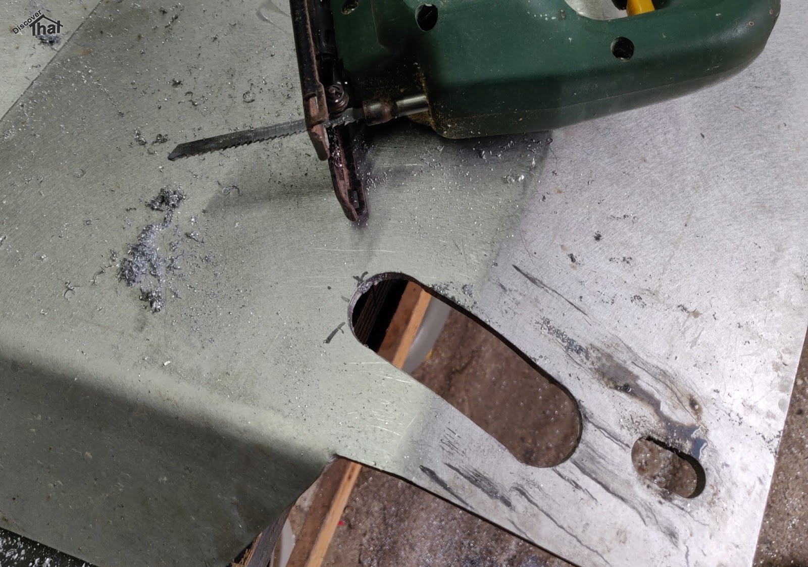
This shows how rusty the steel work of the door was. I am glad I chose to replace the whole door rather than attempting a repair.
There is a foam strip across the door just under the window opening. I'm not sure what it does but I had some, so I fitted it.
The door latch caught me out. It needs to be fitted BEFORE the window runners are installed. There was a bit of back tracking at this stage to get that in.
I gave the catch mechanism a good clean up before refitting.
I used a new handle. I don't know how some of the these OEM and after market suppliers take their measurements because the pivoting puller caught on the door and needed to be trimmed to fit!
The doors I purchased did not come with one of the brackets. I had spotted this so I had
already made the lower hinge side brackets and included a cut out to support the central door locking cable conduit.
The extra bit on the bracket is enough to block the glass when trying to fit that, therefore the bracket has to go on after the glass has been fitted.
This is held on with M6 x 20mm bolts and spring lock washers.
Not only was one bracket missing but the bracket on the other side is in the wrong place. If I had not already had them painted I would probably have sent them back because they were advertised that they were for this age of Defender! I made something to bridge the gap out of a bit of galvanised strapping.
As a slight upgrade, I chose to fit the newer style rubber door seal to the bottom of the doors.
This required an extra couple of 5mm holes, one drilled at either end, just up the side from the bottom of the door.
In addition, all the holes along the bottom of the door needed to be enlarged from 4mm to 5mm. If these doors were designed for a newer model, which is what I had suspected, why did they only have the smaller holes for the older door seal.
They are nicely made doors but I am not impressed by their attention to detail.
I fitted
my design of central locking solenoid bracket.
When refitting the doors it is worth noting that the fillers for the hinge on the A pillar side are not the same as those for the door side of the hinge. The forward ones have cut outs to accommodate the spring of the captive nuts
I replaced the captive nuts. I would have preferred those like the originals I removed, which are proper nuts in a spring frame. Unfortunately, the hole in the bodywork was not quite big enough for me to fit the type I had so I was forced to use spire chimney nuts instead.
It might have been easier with two people but I was able to line up the door myself and use the latch to hold it in place while I got the first of the hinge bolts in.
I made sure the window was open so that I could release the catch from the inside as well as the outside, just in case something did not work properly.
I was pleased with how the door lined up with minimal adjustment.
As soon as the door was on, and the hinges bolted down, I refitted the check strap to avoid accidents.
I had to tuck the central locking solenoid cables up in to the bracket to avoid them fouling on the window mechanism.
In typical Land Rover style, Fender now has one odd colour door :-)
==
Update: 8 December 2018:
I've now done the left hand door as well. I kept track of the time so I now know it took me over 9 hours in two sessions, just for the one door. I wasn't rushing but I'd have to do a few more if I was to ever get any faster.
I remembered to fit the condensation shield or whatever the bit of plastic sheet is called.
I bought some PU adhesive in a mastic tube. A bit messy but I think it's the right stuff to attach the plastic sheet.
I used some 1000G plastic from eBay and the old one as a template.
I will have to revisit the right hand door at some point to fit the plastic to that door.
==