Search This Blog

Showing posts with label lights. Show all posts

Sunday, 23 January 2022

Defender interior lamp connector

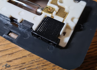
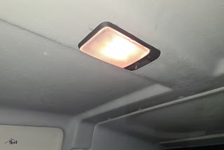
In the process of fitting the rear headlining and specifically a lamp in the rear, I could not find anywhere to get the connector that fits the standard Defender light fitting. They have, in the past, been available on ebay, but not when I was looking. My solution, as usual, was to design and 3D print one.

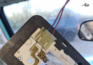
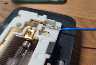
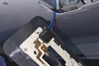
Original Part

I believe that the connector is part number AMR3158.

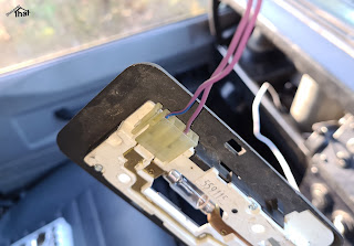
Factory fitted connector


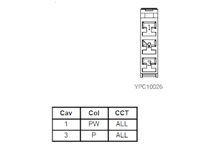
It is connector C357 in the 1997 electrical circuit diagram.


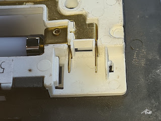
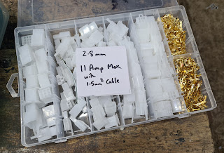
Luckily, the spades fit perfectly into the commonly available 2.8mm connector pins. The 2.8mm connector housings that are readily available online, have narrower spacing between the pins.

Readily available 2.8mm connectors


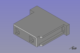
I designed a housing with spacing to fit the lamp, using the 2.8mm pins that I already had. The light only uses two pins 10mm apart.

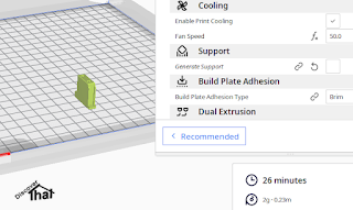
Just off the printer

Snug fit

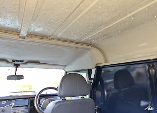
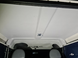
The bare roof and condensation

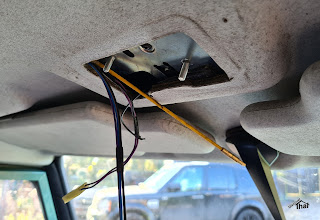
Threading to the front light

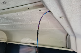
Pulled cables through to the rear

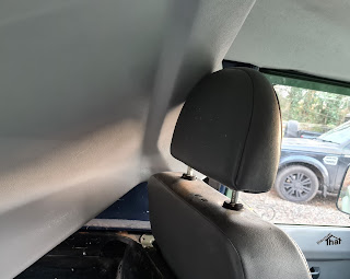
I threaded the cables above the front headlining prior to fitting the rear.

Honestly, it does fit... 

... just about. Needs manoeuvering


This was intended to be an article about the lamp connector but I'll mention fitting the headlining, while I'm here.

The headlining that I fitted was purchased from Simmonites. It's a thin fibreglass panel.

There are a number of trim clips holding up the headlining. I measured the one central trim clip from the centre of the row of trim clips between the front and rear sections. That avoids the risk of movement while measuring. I then marked the row of trim clip holes by offering up the two halves and visually looking at the centres. They were 15mm from the edge and I drilled 8mm holes.


I cut the hole for the lamp holder using a rotary tool and drilled a small hole in the centre spar to secure the bracket.


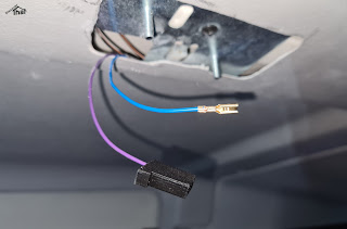
There are three wires, spliced in to the same cables from the front light.

The purple wire is a permanent live. I had purple 0.5mm2 cable available, so it matches the original. The correct method is to disconnect the battery but, of course, I just took care not to touch anything while fitting the crimp. I was happy when the end of the purple cable was safe in the housing.

I had blue 0.5mm2 cable available, so I connected that to the purple/blue cable of the original lamp. It's an earth via the immobiliser ECU. 

There is also a black earth cable, using a 6.3mm spade connector, plugged into a tag cut into the bracket. The bolts are the earth for the lamp.


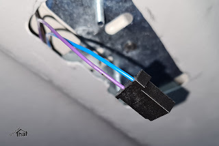
The connector was a tight fit but worked.


Download:

Connector C357 AMR3158 STEP and STL (Zip)


==


Friday, 26 March 2021

Additional workshop lighting

 I've been meaning to add more light in the corners of the workshop for ages.


A few of the jobs over the last week have needed me to use an inspection lamp to be able to see some sides of what I was working on. That nudged me in to getting round to fitting the LED strip lamps that I've had waiting.

==


Monday, 17 April 2017

Defender indicator fix

The indicators stopped working on Fender.

It took no time at all to discover that this was a common problem. The first thing that came to mind was the flasher relay but it appears to be more common for the problem to be the hazard warning switch.


I found a few useful online guides, some of which show the indicator wiring going through the hazard switch:
http://forums.lr4x4.com/topic/25376-hazard-switch-indicators-fault-diagnosis/
http://www.land-rover-blog.co.uk/how-to-fix-a-land-rover-defender-indicator-fault/

It took longer to unscrew the panel to get to the switch than it did to carry out the test and prove it was the hazard switch. Less than 5 minutes to diagnose and a further 10 to re-fit the old, cosmetically damaged, switch, assemble and test all the lights.

A nice quick job for a change.


The cost of the Britpart switch was refunded very quickly by the supplier and I ordered a genuine Lucas part which arrived and I fitted it within a few days.

Sunday, 19 February 2017

Side repeater LED holder

Not a very catchy title but difficult to know what else to describe this as.


One of the side indicator repeaters on Fender had a dodgy connection. Not the easiest thing to repair as it is permanently connected in to the car wiring loom.

There are repair kits available where you cut it out, add a connector on the loom and plug in a new harness. I thought I could make my own.

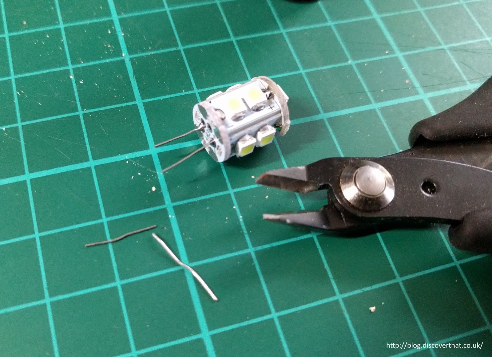
Although it would be a struggle to make a bulb holder I thought I could more easily make an LED lamp holder with the LED soldered on. Being LED they have a long life expectancy so they can be permanently attached. Very much like the LED lamps that are available for the other lights.


There are plenty of LED repeaters in the TD5 or newer style but I have designed my own to fit the 300TDi and older squarer style. These are 3D printed.


I designed the holder with supports built in to the model. That way I can make the supports easier to remove.


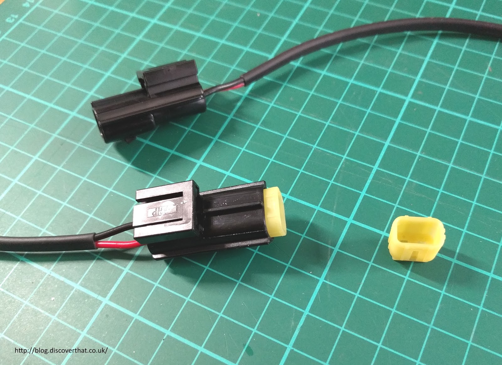
Instead of being connected permanently in to the main harness I have added Econoseal connectors, the same as used on the other indicator lights by Land Rover. To be consistent, I've deliberately wired them the same way round.


If all you want to do is fit an LED to the side repeater, the easiest thing to do is just plug in one of the 501 (W5W) LED replacements. You do have to be careful what size they are.

By trial and error I have found out that many of the W5W replacement LED bulbs are too long to fit the existing indicator repeater lenses. As I had several of these oversize LED lamps I've designed the holder to fit these. Any shorter LED W5Ws would obviously also fit.


Typically the LED's are held in to their plug by simply having the wires bent over. This is similar to the original design of the glass W5W lamps. By unbending the wires the LED section comes out easily and can be slipped in to my 3D printed holder.


The wires on the cable are pushed through the holder and soldered on to the legs of the LED close to the base of the LED.


The holes for the wires in the prototype would only just fit a 1mm2 cable. I've adjusted the 3D model to have larger holes. It will probably still be a tight fit.


The harness is about 350mm long with 20mm exposed at the lamp end and 30mm exposed for the Econoseal connectors.


No more than 10mm of un-insulated leg should remain exposed. The wires are pulled back down so the solder joint is protected and insulated by the plastic holder.

It's important to get the wires the right way round because LED's have a polarity.


The ones I had were marked + and - but they are easily tested with a small 9V battery.


I added the Econoseal connectors and the rubber O ring.


I could have reused the old O rings but I happened to have a box of assorted and one was a good fit.

Left poor fit - Right better crimp results

Worth noting that if you work with the small pins, on things like the Econoseal connectors, a better quality crimp tool makes the job a lot easier.


Once in place the leads are held in to the holder and made water tight by filling the base with mastic. I've used black RTV silicone sealant. It would work equally well with potting resin if you have any to hand.


On the car the old holder is cropped off and the corresponding connector added to those leads.

I found it easier to work through the side light hole as the repeater wires just reached.


Reassemble the car and test all the lights.


Immediately afterwards Shelley took the car for a test drive :-)

==

Cura 3D printer settings

Downloads:
Side Repeater Blend file
Side Repeater STL file
Licence attribution

==