Search This Blog

Showing posts with label Fusion 360. Show all posts

Sunday, 3 February 2019

Cycle lamp bracket

I have created a design for a modified clamp for a Cycleafer bicycle lamp so it can fit a 35mm diameter handlebar.


I decided to do this because the handlebars on Shelley's bike have a diameter of 35mm in the centre. This is a standard but uncommon size. Normally they are between 22.2mm (7/8") and 31.8mm (1.25") but a few are as large as 35mm (1 3/8"). The trouble is, that currently, there are few full size lamps that fit the largest size. The bracket on the Cycleafer lamp does not open wide enough to fit a 35mm tube.


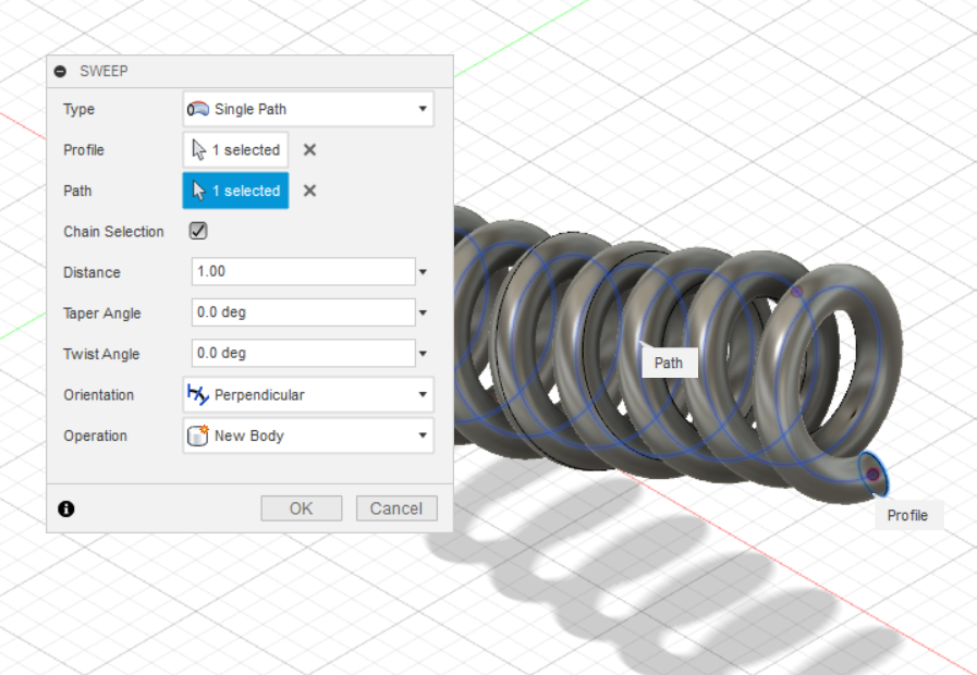
As usual, I have used Fusion 360 to create a model and exported the parts to STL for 3D printing.


The design uses some of the components of the original clamp, including the top plate and the lever for the M4 bolt. The latest revision can reuse the original M4x30mm bolt but it does not give much room for adjustment so an M4x35mm or M4x40mm bolt is preferable.


In addition to the M4 bolt, mentioned above, for use in the latch at one end, it needs an M5x25mm socket cap bolt and nut to secure the other end.


I have printed this using PETG with slightly thicker walls than I would normally use. The walls are 1.6mm thick, to give it a little extra strength.


The first version was usable but I have made several design changes since. I have improved the fit and sloped the front so that the original M4 bolt lever will fit, just about.


I used a couple of drops of High Viscosity Superglue (CA) to hold the M5 nut in place to avoid it dropping out while trying to fit the clamp to the bike.


==

Notes:
Based on the photos in the following review, I believe this clamp will also fit the 'Berlin Standard' bike lamp:
https://www.bestadvisers.co.uk/bike-headlights

Versions:
v32 First release.
v34 Closer fitting cone and a hole for a cable tie as a an alternative, should the thin tongue break.
v42 Reuse the original M4 bolt.
v46 Minor fit changes to the cone.

==

Downloads:
STL models (zip file v46)
STEP model (zip file v46)
Fusion 360 archive (zip file v46)
Licence not commercial


==

Friday, 25 January 2019

Measure a cross section with Fusion 360

This is a very quick tip about how to measure the area and circumference of a cross section of a model using Fusion 360.

First create an offset plane at the position you want to take a cross section of the model.

Create a new sketch on that plane.


Within the sketch, tick the 'Slice' option in the 'Sketch Palette'.


Use the sketch 'Intersect' option from the 'Project / Include' sub-menu.


Either select individual lines or, I found it easier, to use the 'Object' Filter.
That will create an outline with a filled in area, in the shape of the slice.


Now you can use the 'Inspect' then 'Measure' menu item to get the circumference and the area of the slice.

==


Monday, 21 January 2019

Tailors dummy for 3D modelling

I have decided to model a costume helmet. To help with that I have been looking for a full scale model of a human head to use with Fusion 360. I could not find one I was happy with, so I created my own.


One of my main requirements was that it should not impact the performance of Fusion 360 too much. The thing I am creating is the important bit, not what I am modelling it round.

Too many polygons

All of the human 3D models I found are meshes and they are either poor quality or have too many polygons!

Fusion 360 is designed for solid body, not polygon mesh, modelling. Ideally I wanted a native Fusion 360 'Brep' model not a mesh.

I have eventually managed to convert a human body mesh, produced in MakeHuman in to a reasonably tidy 'Brep' solid body model for use in Fusion 360.

It took me the best part of Sunday afternoon with trial and error to get to an end result I am happy with. Fusion 360 can easily convert a solid mesh to a 'Brep' in one go but the result is poor quality and low performance.  The trick is to be able to convert it to T-spline first, to get rid of the reliance on the polygon forms.

The process, that eventually worked, was:
  • Create a generic gender neutral average human in MakeHuman
  • Save that as an '.obj' file
  • Import that in to Blender (2.8 beta**)
  • Get rid of the internal eye sockets and mouth
  • Seal up the eye holes and mouth to make a closed mesh
  • Create a sub-division surface mesh. This was the important bit.
  • Save as another '.obj' file of the higher resolution 
  • Import in to Fusion 360
  • Convert the mesh to T-spline
  • Convert the T-spline to Brep
  • Create the eyes from proper sphere's in Fusion 360 and join to the main body mesh.

Now I have a good quality mannequin model that does not significantly impact performance.


The sub-division surface in Blender creates an all Quad mesh. The use of Quads NOT triangles, was important to get a clean T-spline model in Fusion 360. It did not matter what number of sub-divisions, just one was enough to force the result to quads.


The better looking eyes are a nice to have. I could have done the same process on the MakeHuman generated eyes, as I did on the body. Then I would have ended up with facsimiles of spheres instead of parameter generated spheres.


I will scale the model, as required, to the approximate size for the costume I want to model.

==

Downloads:
Gender neutral human - body dummy (STEP format in zip file)
Gender neutral human - head dummy (STEP format in zip file)

==

** As a side note, the new interface, in Blender 2.8 beta, is so much nicer and easier to use than the earlier versions. It's close enough, to the earlier versions, that I could transition quite quickly but improved in many areas to make it more intuitive to use.

==

Sunday, 6 January 2019

Fusion 360 zoom pan and orbit

I've just spent a frustrating half an hour looking for the instructions to explain what key, button and mouse combinations can be used to control pan, orbit and zoom in Fusion 360.

I've written this post to consolidate the information I found, in to one place.


Just to be clear, I know how to do this with either the onscreen buttons or the default Fusion 360 options but what I wanted was a set of key combinations that work with my Kensington Expert Mouse, which is actually a trackball.


The Fusion 360 default and several of the other options use the middle mouse button for view controls. The trouble is that the button positions on the trackball mean that to use the middle mouse button I have to twist my hand in to a slightly uncomfortable position.


I am therefore, looking for a keyboard alternative to the middle mouse button or the on-screen view controls, that is more efficient and, ideally, a little more comfortable.

Since September 2018 Fusion 360 has had four alternative options, however, I struggled to find details of them, all in one place. Specifically the new Tinkercad settings.


I did eventually find the Fusion 360 help pages on the subject, using the help function within the app. Searching Google or Autodesk's web site was useless. As shown in the image at the start, I have put this together in the hope people manage to find it with less effort than I had to put in.

The Fusion 360 methods work in addition to the selected compatibility option.

For my requirement, only the 'Inventor' option does not use the middle mouse button. I use the F2 and the F4 keys for Pan and orbit, respectively but I continue to use the mouse wheel for zoom.

As an added bonus, this setup also works well with a laptop touch pad.

==

Useful links:
Set your preferences
Keyboard shortcuts

==


Thursday, 29 November 2018

Rope with Fusion 360

When finding out how to represent a rope in Fusion 360 I looked up 'coil following a path' this, it turns out, has a name, 'Helical Sweep.' It is more commonly used for curved springs.


Creating the rope is two helical sweeps at 180 degrees rotation to each other.

I found a pretty good video to show me how to create a single helical sweep:
https://www.youtube.com/watch?v=OudriYF_X8Y

There's no point in going in to detail, the above video explains it clearly.

As a reminder, mainly for me, here are the steps:


  • Create some parameters to make it easier to adjust. [sweepRadius (mm) 10mm, Revolutions (no units) 5, twistAngle (deg) Revolutions * 360]


In model mode


  • Create a path, as a continuous tangent line or curve in a sketch. It will cause an error and fail if it has any awkward kinks from one line segment to the next. I used the 'Tangent Arc' line to make a nice curve.


  • Create a 'plane along path.'


  • Create a sketch on the plane, just created, with a construction line the length of the sweepRadius of the coil and a normal line of any length but about 10mm worked for this model That normal line following on from the sweepRadius construction line. (I revisited this sketch to create the second coiled strand needed for the rope effect, I just did the same lines mirrored.)


Go to Patch mode.


  • Create a sweep following the path, with a twist angle set to the variable twistAngle. That gives a flat helical shape.


  • Create another sketch on the front plane, including 3D geometry.


  • Select the inner edge of the included 3D geometry to create another path.
  • Create another plane along path, selecting that helix. Move the plane to zero on the path.


Back to the model mode

  • Create a sketch on that plane, with a shape centred on the start of the point of the path, usually a circle but could be any shape.


  • Select the shape and create a sweep along the helical path.


I needed two of these coils intertwined to make a nice looking rope.

I used the same sketch for the sweep radius but created another construction line and normal line in the opposite direction from the centre.
Using the same spiral sweep I created another coil.

I needed to patch the patches and stitch them to make them both solid models. I adjusted the diameter of the strands until they just merged, which was 20mm.


I textured them using 'weathered leather,' as that was the best I could find to match a hemp type rope.

==

For the parameters I ended up with:
sweepRadius = 10mm
Revolutions = 5
This was over a 300mm length of rope.
Each of the two rope strands was 20mm diameter.