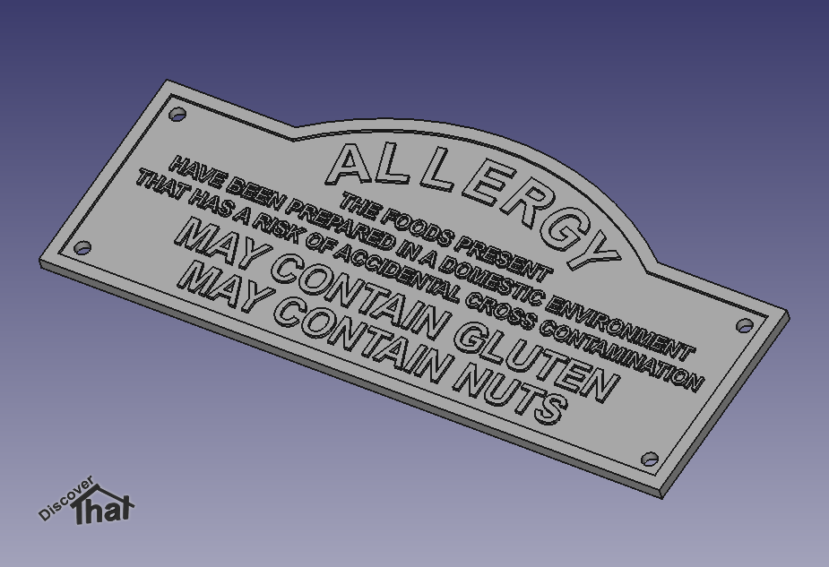
For the last couple of days I have been printing some signs.
They are mainly flat with raised lettering.
Due to various failures I have been trying different types of filament among other things to fix the issues.
The results have led to some conclusions and preferences.
Filament choices in order of preference:
Rigid.ink PLA Plus
This is the best at the job so far. It stays flat on the glass with no warping even on the largest size flat prints.
It's not perfect though. The end of the spool is wound so tightly that the Ultimaker 2+ extruder struggles to get the last half dozen layers of coils off of the spool. That's a lot of wasted filament!
My guess is that the tight loops press against the inside of the Bowden tube so I can't even use it loose from the spool.
Heated to 225C with the bed at 45C.
The results have a nice tidy surface finish with sharp edges.
Takes spray paint well.
Update: Rigid.ink is no longer available. They suggest trying https://shop.3dfilaprint.com. I have used them before but have not got any in stock to try out. I'll update this article when I have tested some.
I'll probably try their Premium PLA:
https://shop.3dfilaprint.com/filaprint-black-premium-pla-285mm-3d-printer-filament-1380-p.asp
ColorFabb PLA/PHA
This was a lot better than standard PLA. It stayed flat on most prints with only a slight tendency to curl.
I get best result running it hotter than the suggested.
For me I heat to 215C with the bed at 60C.
The surfaces are nice and tidy. The raised details have a very slight bulge at the corners. If I was not comparing to other prints I would not have noticed.
When spray painting it is obvious the surface is porous along the print lines.
3DFilaPrint.com PLA
This would not stay flat. Even before it had done the third layer the edges of the brim were curling up and by the time the print had finished, the main body had lifted by a couple of millimetres at several corners.
I've used this successfully on other prints. It just does not like the thin flat prints.
Printed at 210C with the bed at 60C
Inconsistent Information
Several of the manufacturers provide guides or printed temperature ranges on their boxes. This information often changes. One manufacturer has three different heated bed temperature suggestions for the same filament, one on their web site, a different figure on a card supplied in the box and yet another range on the side of the box!
I no longer take the instructions as fixed rules. I use the suggestions as a guide to get me in the right direction. Trial and error is the only sure way.
==
Glass Thickness
As far as fixing the various issues, I think the glass is the main problem.
One of the problems is that the prints would warp. This always started in the rear right corner. For many prints that was the only issue but invariably the print would lift so high it would impede the print head and ruin the print.
I can only assume there is a slight inconsistency in the glass thickness. If I avoid printing on the rear right quadrant of the print bed, I get much more reliable results.
The affected area extends about 50mm from the right hand edge to about half way forwards from the back edge.
I managed to avoid this by rotating the largest prints and they have all worked since.
I plan to experiment with bed levelling to see if by deliberately setting a greater distance at the front left corner I can get better reliability at the rear right.
==
Worn Nozzle
Before I was able to get anything working I had to replace the nozzle.
The filament would flow for a while then get straggly. Small blobs every few millimetres with thin thread like strands between!
I don't know if the hot end nozzle was contaminated or worn but after I replaced it the flow was even again.
==
Printed with Thicker Layers
In the past I have found that thicker layers are troublesome. Now that I have done some more trials, I am able to successfully and reliably print with the following settings:
Nozzle: 0.4mm
Layer height: 0.24mm
Edge, top and bottom thickness: 1.2mm
Print speed: 60mm/s
Travel speed: 120mm/s
Adhesion: 7mm brim
Bed: Glass with hairspray (once in a while)
Rules of Thumb
I found on an
Ultimaker forum, a rough guide to layer thickness and print speeds.
This approximately lines up with my experience, so I will use it from now on, rather than my usual guess work.
Maximum layer thickness: 3/4 of the nozzle diameter
e.g. 0.4mm nozzle can print a layer up to 0.3mm thick.
Maximum speed
The maximum print speed is determined by how fast the filament extruder can feed.
Stock Ultimaker 2 extruder, maximum throughput of 2.85mm filament: 7mm
3/s
Calculation: Nozzle diameter x layer height x speed = throughput area
e.g. 0.4mm x 0.3mm x 40mm/s = 4.8mm
3/s
Maximum speed calculation = Maximum throughput / (nozzle diameter x layer height)
Therefore the maximum speed is likely to be:
7mm
3 / (0.4mm x 0.3mm) = 58mm/s
I have an Ultimaker 2+. According to the
Ultimaker web site, the Ultimaker 2+, can print up to 16mm
3/s with a 0.4mm diameter nozzle. It has a maximum travel speed of 300mm/s.
In theory, therefore, I could double the above speeds. In practice I have not been able to a achieve speeds much faster than the above calculations.
I tried, just as a double check. 0.4mm nozzle, 0.24mm layer and 90mm/s at 210C with PLA = 8.6mm
3/s. It came out lumpy and did not stick to the bed properly.
The kit was clearly capable of pushing it at that speed but it would need a lot more tinkering to get close to something usable.
Nozzle Temperature
The hot end temperature is far more trial and error. That is partly because the thermostats in the printers are not that accurate.
Most manufacturers recommend starting at the low end of their suggested range of temperatures and work up.
According to most vendors, 2.85mm diameter filament tends to need to be about 5C hotter than 1.75mm filament for the same speed, so for a standard Ultimaker, which uses 2.85mm filament, start at 5C above the manufacturers suggested lowest temperature.
Increase the temperature for faster throughput. Alternately, it would be simpler to increase the speed for lower layer heights so the throughput is always roughly the same area per second, therefore the temperature could remain the same for all prints.
==