Search This Blog
Saturday, 1 August 2026
Miniature paint schemes reference
Sunday, 12 July 2026
Dry brush for edge highlights
I'm sure there are lots of reasons to use dry brushing. It's a technique I like to use for highlighting texture on fur and hair and for edge highlighting.
I can remember the first time I successfully used dry brushing. That was for fur, well over 30 years ago. It was on a troop of Ork Wargs. I was so pleased with the results. It is when my painting results changed from "just colour on tin lead" to "these look nice."
I have had good results with metallic colours. Silver dry brushed on to black and copper dry brushed on to brown. I now think I have the technique sorted for edge highlighting with dry brushing.
| The edges of the containers and barrels are highlighted |
I've written these notes as a reminder to myself.
Edge Highlight Colour
I find that I need to use a lighter brighter colour than I expect.
| Edge and curved surface highlighting |
Light grey on black, white on light grey, very pale green on dark green etc. If in doubt, regardless of the base colour, I might use light grey or white.
I like my models to have a lived in look. I often use a black or sepia wash and then add highlights. A similar technique to edge highlighting can be used to add a little brightness to curved surfaces such as shoulder pauldrons and the pipes in the above picture.
Brush
I've tried specialist dry brushing brushes, but I find those too large for miniatures and their round shape make them difficult to direct the brush to the specific edge that I want to hit.
What I do use and my favourite is a makeup brush designed for eyeshadow. They have soft flat bristles about 8 to 10mm wide.
These are great for most edge highlighting, from small scatter terrain down to delicate miniatures. Being flat I have two choices of direction. The wider is good for long edges and by dragging the brush with the narrow face forward the brushes can get into fairly small spaces. In that rotated position they have a long enough stoke to deposit sufficient paint.
In tight spots where I need to avoid getting paint on adjacent surfaces, I use a 3mm angled shader brush. Again a flat bristle brush. This gives me lots of control and I can be very specific about which edge is highlighted.
Paint Loading
This I find a bit trial and error every time.
For cleaning I use a sponge with just a finger or two dipped in water to dampen it. I also use this to slightly dampen the bristles before I start loading the paint.
Most of the time I use undiluted paint for dry brushing. I find that if the paint is watered down, it smears rather than it catching the edges.
I like to get paint on all sides of the tip of the brush and then wipe nearly all of it off on a cotton cloth. If I can see paint depositing on the cloth, there's usually still too much paint on the brush. That's not a perfect guide, just a starting point.
My first stoke will be very light to see how easily the paint applies and either add or remove paint, as I feel. It varies by colour. Some paints work with very little effort and others need constant care to get the amount of paint on the brush just right.
Technique
I lightly drag the brush over the edge I want to highlight and can usually see the layer build up as a fine line. As the paint gets used I need to apply a little more pressure on each stroke.
The more I've use the technique, the more control I've gained about where I get the colour.
==
Sunday, 5 July 2026
Less is more painting miniatures
Very Quick Process
- Prime with black from a rattle can - this had been done weeks ago
- Airbrush army dull green all over
- Dark grey paint in the folds behind the knees and between the legs
- Black wash all over
- Dry overnight
- Dry brush in light green to highlight some of the edges - using an 8mm flat makeup brush
- Paint the eye lenses in yellow - using a 00 short bristle sable brush (W&N s7 miniature)
- Tidy up the yellow - edge in black wherever I had gone over with the yellow
- Paint in any details I want, could be; missile caps, belt buckles, sergeant's pauldrons, banners etc.
- Paint all the weapons black
- Dry brush the edges of the weapons in light grey - using a 3mm wide flat angled shader brush
- Base using grass flock which sticks to thickly applied brown paint
- Paint the edge of the base in black
- Dry overnight
- Clear matt spray varnish
Thursday, 23 April 2026
Post-battle report
We had another great couple of games of One Page Rules - Grimdark Future a couple of weeks ago. Following that I've made a few improvements ready for the next encounter.
Each time we've played, the table setup has looked better. I've had more variety of scenery prepared and much of it is painted. I'm particularly pleased with the tyrannosaur skeleton. Modelled from a complete structured cut and assembled to look part buried and useful as cover.
I've added to my modular buildings. For the last game I had just finished the alien fort.
The idea is that the base colours are the same, so that all the components are interchangeable. I found I was a little short of some of the bits to finish off the edges so since then I've printed and painted some more bits.
I've honed the painting technique to be as quick as possible. I've skipped the primer because the Rust-oleum Switch Limestone spray gets good coverage and adhesion on the PETG without the need for a primer.
I've watered down the off-black emulsion wash a lot more. This gives the effect I want without the need to further dry brush over the top. I remembered to mask off the floor, so that could be finished just by a quick dry brush of Vallejo sombre grey. This quicker process means that the basic building blocks can be ready to use very quickly.
There's always more scenery to paint. Like the buildings, I found a quick method for these rocks. Prime in grey then a sepia wash over the top changes the grey to a more khaki colour. This is then dry brushed in a very light grey to get the finished result.
Lastly for now, a scoreboard. That's something I wanted for our previous games, but it was always too far down the list of jobs.
I had tried to buy something but everything that included appropriate counters was a size more suitable for a stadium rather than an intimate tabletop game where we had squeezed it into our living room!
There were a few 3D printable designs but none that I could find were quite what I wanted. As I find fairly frequently, I had to design and print my own. It only took two iterations to get exactly what I was after.
The rings have an octagonal cross section and clip into matching holes. The team names and even the turn name can be swapped out.
Unusual for a 3D print of this size, I've printed it solid. This gives it a nice weight.
I'm sure I will continue to add and paint more scenery and I've starting to assemble another army. I'm looking forward to the next match.
==
Sunday, 1 March 2026
Painted gold visor effect
I have a lot of sci-fi miniature infantry to paint and many of them have closed visors. Inspired by Halo's Master Chief, my initial idea was to paint the visor gold. With a few images in front of me I soon realised that needed more thought.
I stumbled across an easy method that I think works to produce an acceptable visor at a distance.
To be clear, I am sure there are more attractive solutions with layering and blending, but that is time consuming to do for a tabletop army.
Step 1 - base coat in black
Step 2 - brown dry brush
Step 3 - gold lines
To get an initial reflection effect, I paint two vertical metallic gold lines. They both have a gap between the peak and the start of the line and end before the lower edge of the visor. The first is about a third of the way round the visor facing the assumed light source. The second is shorter and between that line and the centre line.
Step 4 - gold dry brush
Next, I dry brush the same metallic gold very gently over the whole lens.
I have a narrow makeup brush that I use for this. It is small enough to restrict the area the dry brushing affects.
Step 5 - gloss clear coat
Adding a gloss clear coat is not essential. I usually clear matt coat the entire model to protect it for handling. The gloss clear coat is added only to the visor area, after the matt coat has dried.
==
Wednesday, 23 August 2023
Defender hazard and indicator light diagnostics
Defender 1984 to 2016
Hazard and Indicator Lights Diagnostics
“Many problems with the indicators are actually faults with
the hazard switch.”
Wiring Differences
The various models of Land Rover Defenders from 1984 through
to 2016 have similar wiring but have slightly different colour wires
connected at the hazard switch.
The wiring colours are written as the main colour first with the stripe colour after. As an example, a light green wire with a white stripe would be written as Light Green/White (LGW). A grey (slate) wire with a brown stripe would be written as Slate/Brown (SN).
After 1998, the colour of the ignition feed changes to White/Green and the permanent feed to Purple/Brown.
Operation
To better understand the significant functions, only the indicator operation is described in the following. The panel
lighting and tell-tale light functions are not noted here:
|
When off (not
depressed) Indicators
can be used. |
+12V to the
flasher relay is supplied from the ignition feed. The ignition
has to be in position two for the indicators to work from the column
controls. == +12V ignition,
Dark Green or White/Green, depending on the model year, is connected to the Light
Green wire to the flasher unit. |
|
When on
(depressed) Hazard
lights in use. |
+12V
permanent feed is connected to the flasher unit. The return
from the flasher is connected to both the left-hand and right-hand side
indicators. Both sides
indicators will flash. == Permanent
+12V Purple or Purple/Brown wire is connected to the Light Green wire to the
flasher unit. The Light Green/Brown return wire from the flasher unit is connected to both the Green/Red and Green/White feeds to the indicator lamps. |
Diagnostics
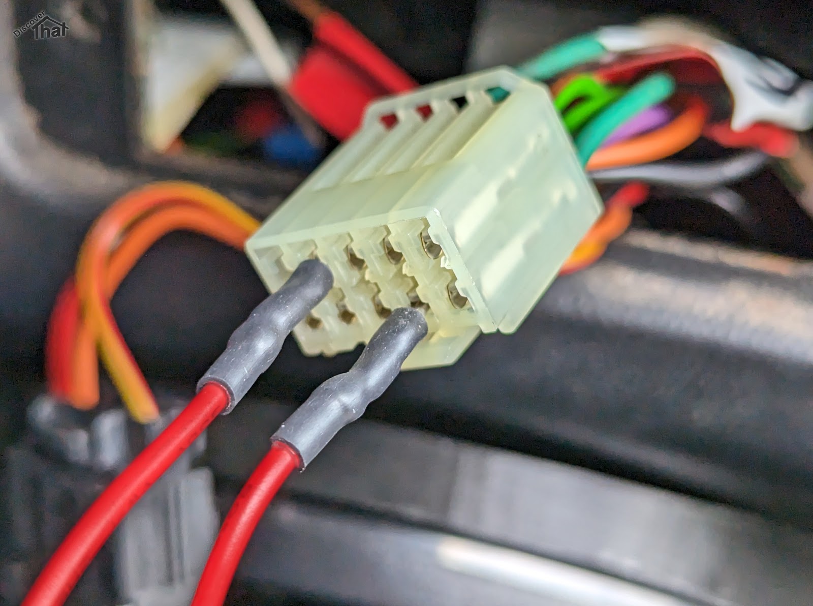
I like to make up a test wire using an inline fuse. This is to avoid
mistakes accidentally shorting out a live to earth. A 5A fuse is suggested. It
needs to be less than 10Amp to avoid the fuse box fuse blowing first.
Most indicator faults can be diagnosed via the hazard switch
connector.
|
To Test |
Method |
Expected
Result |
|
Indicator wiring |
At the hazard
switch connector. Connect the
permanent live, Purple or Purple/Brown, to the Left and Right indicator
wires, in turn. Left is
Green/Red Right is
Green/White |
The
indicators on one side would illuminate. Not flashing. |
|
Flasher unit and
indicator controls |
At the hazard
switch connector. Connect the
permanent live, Purple or Purple/Brown, to the Light Green flasher feed. Operate the
indicator stalk switches. |
The appropriate
indicators should flash. |
|
Ignition
live feed |
At the hazard
switch connector. Repeat the
above two operations using the ignition feed Green or White/Green wire, in place of the Purple wire. The ignition switch must be in position two. |
Same results
as above. |
|
Indicator
stalk switches |
At the
indicator stalk pins. Bridge the Light
Green/Brown common wire from the flasher to the indicator wires, in turn: Left is
Green/Red Right is
Green/White |
The
appropriate indicators should flash. |
Just in-case anyone notices. The photos are from a 1998 300TDi re-wired to use the switches from a newer 2002 onwards TDCi.
Troubleshooting
|
Bridging any of the wires at the connector works but using the switch fails. |
Clean the
connector pins on both the connector and out the back of the switch. If the above
fails to resolve the issue, it will be necessary to replace the switch. |
|
Either
bridging of the permanent or ignition wire tests fail. |
Check the
appropriate fuse. |
|
The indicator
lamps illuminate when connected to a live but do not work through the flasher
unit. |
Remove the
flasher unit from its socket and clean the pins. If the above
fails to resolve the issue, it will be necessary to replace the flasher unit. |
Cleaning Connector Pins
This can be done with a pencil rubber or more commonly with
fine sandpaper. A needle file can be useful to get into confined spaces.
Where the electrical interface is inaccessible, a chemical
contact cleaner can be used, however this often also needs the connector to be
inserted and removed a few times to assist the cleaning process.
If the connector pins do not hold tightly, small, pointed
nose pliers can sometimes be used to gently close up the female portion of the
connector pins.
Fuses
Ignoring the main fuses and links because there would be
other symptoms if they had blown.
|
Up to 1998 300TDi |
Permanent
Feed, Purple – Central interior fuse box Fuse 1 (15A) Ignition
lighting feed, Green – Central interior fuse box Fuse 3 (15A) |
|
1999 to 2001 Early TD5 |
Permanent
Feed, Purple/Brown – Central interior fuse box Fuse 31 (15A) Ignition
lighting feed, White/Green – Central interior fuse box Fuse 21 (10A) |
|
2002 to 2016 Late TD5 |
Permanent
Feed, Purple/Brown – Central interior fuse box Fuse 31 (15A) Ignition
lighting feed, White/Green – Central interior fuse box Fuse 21 (10A) |
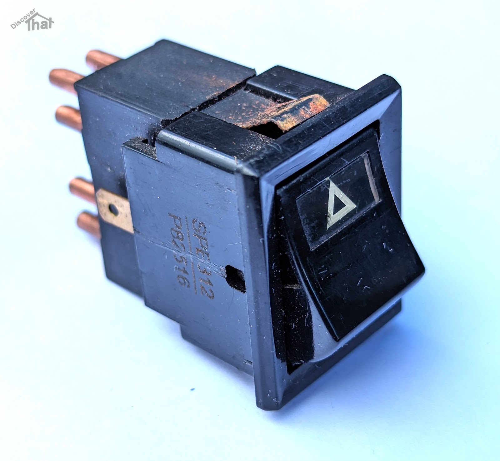
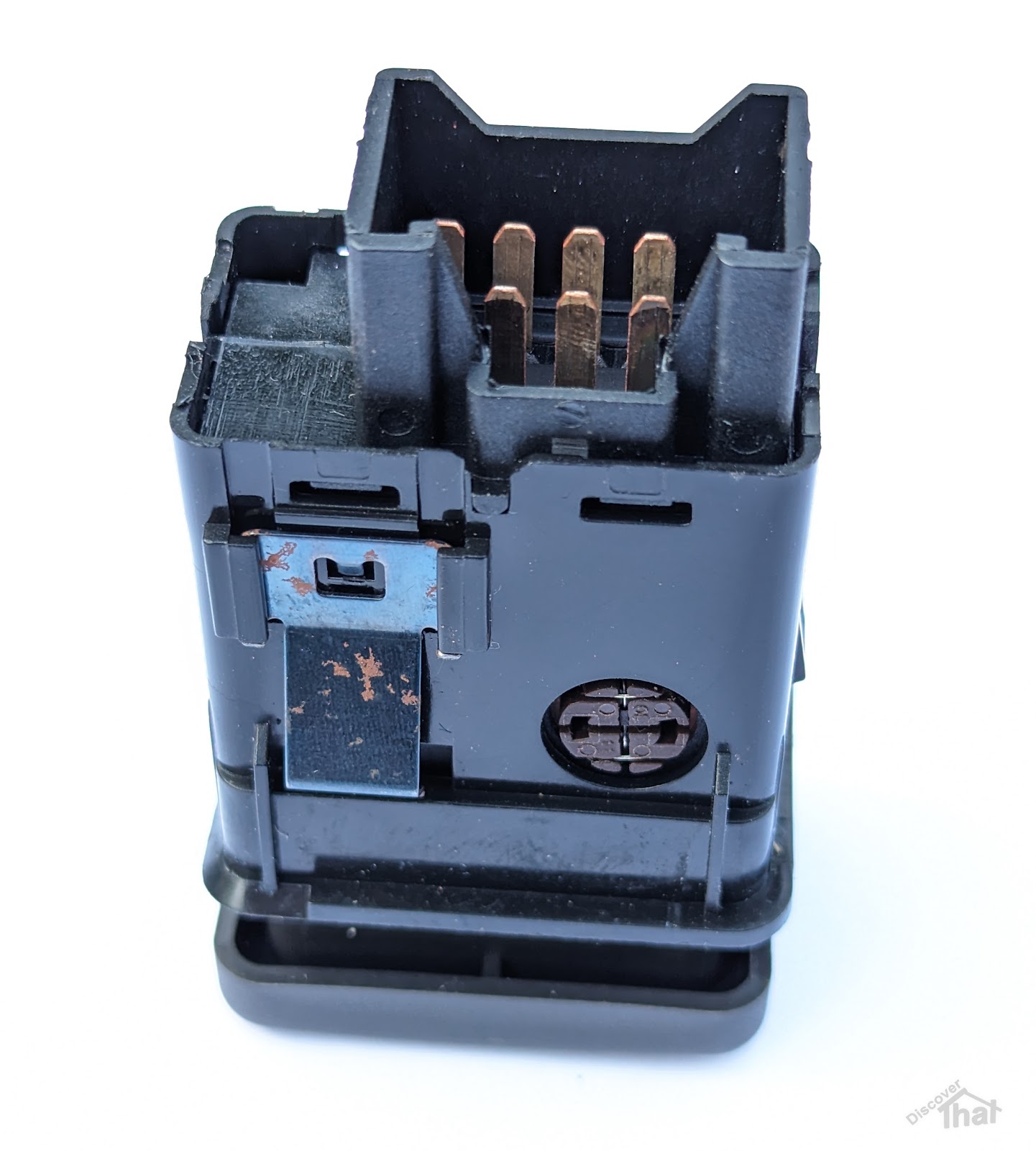
Switch Types
|
Defender 1983 to 2001 TD, 200TDi, 300TDi and early TD5 YUF101490
Lucas switch |
|
|
Defender 2002 to 2016 Late TD5 and TDCi Puma YUG000180LNF |
|
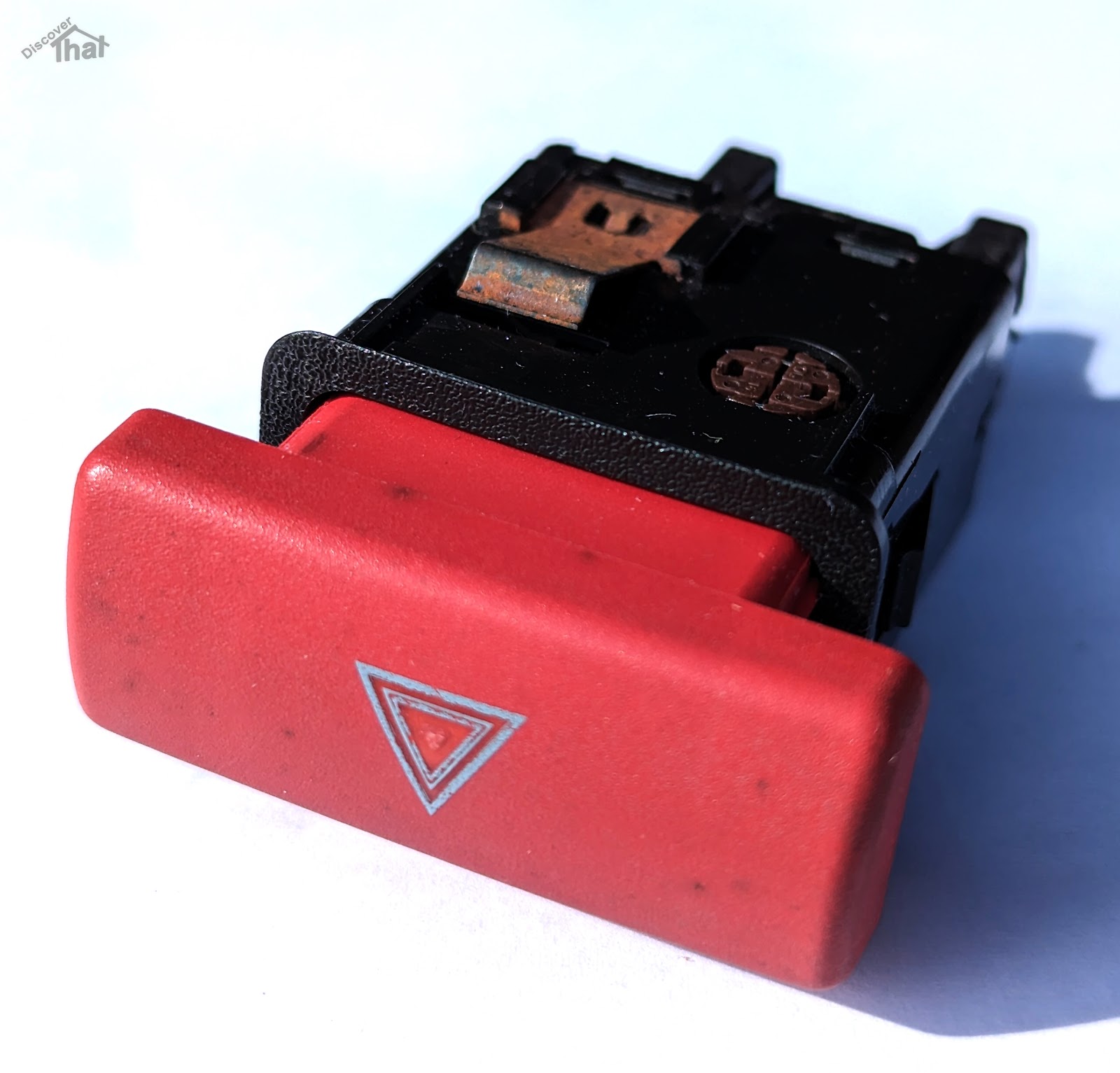
|
Freelander 1996 to 2002 YUG102220 |
The early Freelander hazard switch body is the same as the late Defender. It uses the same wiring and connector but the key cap is different. In the event that a Defender hazard switch is not available, that era Freelander switch can be used as an alternative. In order to make it fit the dash panel, the key cap needs to be carefully removed and swapped over with the Defender key cap. It is held on by two plastic clips, one top and one bottom.
|
I'll add to this if I discover any more tips.
I only have direct experience of a 1998 300TDi and a 2009 TDCi. All other information is taken from manuals and third-hand information. There are likely to be exceptions and some cars, like my own, will have been modified.
==