Search This Blog

Sunday 30 April 2017

Tips for using Visual Studio Code with a NodeMCU

I am now working on the code for my project. There are a few things to know to be able to use the Ardino libraries for a NodeMCU with Visual Studio Code as the IDE.

Here are the things I needed to know:

Serial Monitor

You need to open the serial monitor BEFORE uploading the sketch to the device.


Go to the View Command Palette (F1) menu and select:
Arduino: Open Serial Monitor

If the serial monitor is not already open, any initial serial output will not be displayed.


Once open, set the COM port and the speed. I always use 115,200 baud.

If the serial monitor is already open, the implementation of the Arduino Visual Studio Code extension that I am using, temporarily disables the serial monitor for the upload and then pops it in to view and connects immediately after uploading the sketch. This is very handy behaviour.

Keep an eye out for the monitor being closed due to errors! It just needs to be re-opened.

Uploading Sketches

This has the same behaviour as the Arduion IDE. It compiles and uploads as one function.

Go to the View Command Palette (F1) menu and select:
Arduino: Upload (Ctrl+Alt+U)


This displays the OUTPUT window for the Arduino.
When complete, if the serial monitor is already open, it will re-connect the monitor and display the serial monitor window, usually.
Where I have had errors I have found the monitor does not automatically re-open!

The Config file


If, like me, you use a NAS box for storage you might end up having to enter a library path to an IP address or host name.
If you do that, remember to double double escape '\\\\' the initial path variables in the config file:
c_cpp_properties.json

{
"configurations": [
{
  "name": "Win32",
  "includePath": [
    "C:\\Users\\you\\AppData\\Local\\Arduino15\\packages\\esp8266",
    "\\\\192.168.0.100\\users\\you\\Documents\\Arduino\\libraries"
],
  "browse": {
  "limitSymbolsToIncludedHeaders": false,
  "path": [
    "C:\\Users\\you\\AppData\\Local\\Arduino15\\packages\\esp8266",
    "\\\\192.168.0.100\\users\\you\\Documents\\Arduino\\libraries"
]}}]
}

==

I'll add to the above as I learn more.

==

Bolt cap

This is a cap used for finger tightening bolts. The bolt is glued in and the cover fitted to hide the bolt top.


3D modelled by myself and 3D printed. The edges have been raised in places to provide grip.


The model included in the download is for an M6 bolt but it could easily be resized to fit any.


I used a 16mm and a 6mm punch to create rubber washers from an old bicycle tyre inner tube.


They are destined for the light protecting grills on the front of a Land Rover Defender.

Original M5 bolt (top) next to the replacement M6 bolt (bottom)

The nuts in the bodywork had pulled through and had to be replaced with a larger size. Therefore the original M5 bolts no longer fitted.


The new M6 versions look very similar to the originals.

==

Downloads:
Bolt Cap Blend file
Bolt Cap STL file
Licence attribution

My designs on YouMagine.com

==

Wednesday 26 April 2017

Online flowchart tools

Today I decided to have a look at online tools for creating flowcharts. There are loads so I am going to try a random selection out and make notes here.


I use flowcharts to detail some parts of my software code. In this case it will be for the ESP8266 driveway alarm system I am working on.

When designing my applications, in the past, I have used a combination of Microsoft Word and hand drawn flowcharts which I then scan in.

I thought that by now there must be a low cost online solution to flowcharts so I can skip the scanning stage and have them available to edit wherever I am.
I have used Microsoft Visio in the past but this is an expensive tool for the small number of uses I have for it.

I tried the Office 365 version of PowerPoint but this was limited and very awkward, making it slow to use for this purpose.

I'm after a tool that is nearly as quick or quicker to use than my hand drawn paper charts.

As usual, in no particular order:

Draw.io

Draw.io went straight to the create a document screen. No messing about, get to work immediately.

If there is any pricing I could not find it. At the moment, I am assuming it is free!

There is a banner on the screen with a link to GitHub and the open source code is all there.
https://github.com/jgraph/draw.io
I noticed it is actively being updated as the dates were today.

Draw.io uses your online storage or a local file to save your work.


I chose OneDrive and obviously it needed permission to access that.


It is very easy to use. Drag, copy, link with arrows, all works in the most obvious way. At least to me.

Big arrows appear to create the link from, little crosses appear where you can connect the link on to. I could select groups and move them all about together, I could move things to the top or bottom of a stack. If I moved shapes the linked lines followed them, as long as I had correctly made the connection. It was very quick to link an arrow if I had not already done so.

The shapes can be manually edited so I found I could change the shapes but keep the text by copying and pasting the shape code from one object to another. Easy.
There are a useful number of shape sets to choose from. I mainly used the traditional flowchart shapes but there's a whole set for UML diagrams among others.

The files are saved as HTML with something embedded that opens the chart on the draw.io web site. It works well from a file on my local machine but OneDrive treats it as a text file. Probably a sensible security feature but not ideal for editing previous drawings from the OneDrive end. If you open the draw.io web site you can quickly browse to you existing draw.io documents and open them that way.

You can also save to a selection of image formats, such as JPG and PNG.

So far I am very pleased with draw.io. Just what I was looking for.

I found some reviews, after I had used it:
http://blinklist.com/reviews/draw-io
http://uk.pcmag.com/drawio
http://uk.pcmag.com/software/88898/guide/the-best-flowchart-and-diagramming-apps-of-2017

Creately

This is $5 per month or all diagrams are public. I haven't tried it out.

GenMyModel

Free for small projects but the results are public.
Not what I was after.

Web Sequence Diagrams

I didn't get the hang of the concept. It was like coding to create the flowchart to create the program!


I could create a basic diagram with quick icons then I could probably fine tune it with manual edits. It was not what I was after so I didn't do much with it.

Draw Anywhere

30 day free trial. It required Adobe Flash Player, so that stopped there. Old technology, not worth the hassle, in my opinion.

Lucidchart

Apparently there is a free trial version but to find out the limits I would have needed to sign up. I don't like sites that don't tell you the details until after you have signed up for something.
The basic version is £5.45 per month.

SmartDraw Cloud

SmartDraw has a desktop product that I have used before. It used to be a competitor to Visio I assume it still is. The cloud version did not have any details before signing up. I decided not to try this one at the moment.

Gliffy

The free trial looked like the sort of thing I was after. Very similar style to draw.io. I ran out of time to give it a full tryout but at first glance it looked good.


What I tried worked well. It had a traditional toolbar at the top to change from, lines, to move about or add text. Speedy to use. To save documents it was necessary to sign up, which I didn't do.

While I was browsing the Draw.io source code I came across a folder for Gliffy. That would explain why the two have so many similarities.
https://github.com/jgraph/draw.io/tree/master/src/com/mxgraph/io/gliffy

Conclusion

The first product I tried, draw.io, was the best for me. I'm not sure if I will find any limitations or gotchas with extended use but I'll update this page if I do.

Saturday 22 April 2017

Lucas 10AS connectors

The Lucas 10AS unit is used for a few functions in various Land Rovers. It was the standard immobiliser and alarm for many years in Land Rovers and Range Rovers c.1995 on.


A similar 2 button key fob (plip) was used for the Lucas 5AS, 10AS and the 27VT used in the Freelander 1 but not all the internals were the same. Some do not have the workings to activate the passive immobiliser coil required for Defenders and Discoveries but not the Freelander (from what I've read).


They all seam to be called 17TN key fobs but some are also called 3TXD, which is on the circuit board. If you are buying one, it probably needs to say that it will work with a Defender, to be sure it has the components required for the passive immobiliser.

The 10AS was used to control the interior lights so they fade out. In some models it controls the central door locking.


I plan to add central door locking and I would like to use the original style remote controls.

OBD connector

Lucas 10AS with connectors

The first step in achieving that is to rig up a test setup for which I needed some connectors.

These are a standard component, still in use. They are from the TE Multilock range and use the 040 and 070 terminal sizes. All of the Multilock bits together came to less than £10 from RS Components. I bought the OBD socket from e-bay for about £2.


Larger terminal

Smaller terminal

The RS Components and the manufacturers part numbers can be seen in the photos.
The manufacturers parts numbers are:
173851-4 Green connector housing
174516-6 Grey connector housing
173631-1 070 crimp terminal (for the green and outer pins of the grey sockets)
173716-1 040 crimp terminal (for the centre pins of the grey socket)

The last digit following the dash for the plugs, indicates the colour; -6 = grey and -4 = green.

The idea is to rig up a test loom so I can check the function of the door locks without dismantling the dash and crawling round inside the car until it is all working.

==

Related articles:
http://blog.discoverthat.co.uk/2018/06/central-locking-poc.html
https://blog.discoverthat.co.uk/2018/06/swapping-10as-immobiliser.html

External Links:
http://www.gomog.com/allmorgan/LandRoverSecurityManual.pdf

==

Wednesday 19 April 2017

Installing Visual Studio Code for ESP8266

Visual Studio Code is Microsoft's very light weight editor. Available for Windows, Mac and Linux.


To get it to work with the Arduino and the ESP8266 you need to add two extensions. The whole design of Visual Studio Code is so that it can easily be configured for any development language using these extensions.

Before you do that install the Arduino IDE.
Like most of the IDE's I have tried, they rely on the Arduino IDE for all the libraries.
I also made sure it was fully configured with the add-on for ESP8266 before I continued.

With that installed it's time to install the extensions.

The first extension is for C++ and it is by Microsoft:
https://marketplace.visualstudio.com/items?itemName=ms-vscode.cpptools

The other extension is for the ARduino and for this there are several choices. I've used the Microsoft one:
https://marketplace.visualstudio.com/items?itemName=vsciot-vscode.vscode-arduino

I have not tried them but here are some others for the Arduino:
https://marketplace.visualstudio.com/items?itemName=steveyin.arduino-vscode
https://github.com/fabienroyer/VisualStudioCodeArduino
https://marketplace.visualstudio.com/items?itemName=moozzyk.Arduino

They are actually very easy to install.
There is a short code you can copy in and that displays the appropriate list of extensions:
Go to file (Ctrl-P): ext install cpptools
Go to file (Ctrl-P): ext install arduino-vscode

My initial install did not go to plan. I ended up spending more time than I expected but that was down to issues with my machine setup not as a fault with the application!

Important: You must be able to run JSON files. I had problems because my firewall was blocking them for some reason! I had to bypass that.


Important: Windows 10 security, Developer Mode might be restricting installs, On my machine it was restricting me to only install store apps. I had to change mine to Developer mode to get the extensions to install.

Extensions appear in a side bar. Select the appropriate one and press install.


Once installed, either restart or simply press the reload button that appears. Only then do the extensions get downloaded and installed.


Now it should be ready to go.

All projects need to be in their own folder. You can open individual files but without a corresponding folder there is nowhere for the application to save it's settings.

Once you have a new .ino file or project open, the status bar displays Arduino specific content.


There is a tiny selection at the bottom on the status bar to select C++ and the board etc.
You can change the settings and more from the Command Palette menu that appears when pressing F1.

At this point Intellisense worked up to a point. Where the classes are internal to the code, it worked fine but it could not find the external libraries and dependencies.

To get the rest of the Intellisense and probably the ability to compile you MUST select the board AND the COM port on the status bar. That appears to be the trigger to read the appropriate libraries.


This can be a pain if you do not have the Arduino or ESP8266 connected to the PC because you might not have any COM ports. Also, try selecting the COM port first. That's what I did.

That got things working for the main Arduino classes but I was still missing the ESP8266 classes.

That appears to be caused by a slight error in the install. It automatically includes a path that is too specific.

It can be fixed by following the light bulb link from within the code file.


That opened the file c_cpp.properties.json file.


I moved the path lower down the tree, to this:
"C:\\Users\\jcb\\AppData\\Local\\Arduino15\\packages\\esp8266\\hardware\\esp8266\\2.3.0"

The application searches all sub-folders unless you tell it otherwise, so that picked up all the class files needed.

I also included all the Ardunio libraries:
"C:\\Program Files (x86)\\Arduino\\libraries"

It is necessary to restart Visual Studio Code for the change to take effect.


Once that was all working nicely it was time for a compile and upload.

That option can be found from the F1 Command Palette list. Not the most convenient place but it's OK.

It didn't work first time because I had trouble with using a USB hub. I had to swap to a physical USB port directly on the machine but after that it worked at 115,200 baud.


Not an extensive test so far but it's working. I like the Intellisense in Visual Studio Code and the style of the app. I'll try this for longer to see if it makes coding that much easier.

==

Update: 20 May 2017
The latest updates stopped Intellisence working with my Arduino code!
Versions: Visual Studio Code 1.12.2 with the extensions, Microsoft C++ 0.11.1 and Microsoft Arduino 0.2.2


Something has messed up the Intellisense engine. The code would still compile but there were lots of red squiggles under code that was clearly valid.


I managed to find a setting which changed the Intellisense behaviour and put it right! You have to open the File -Preferences -Settings and browse down to the C++ configuration section.


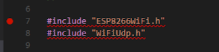
With the 'Default' engine the code looks wrong


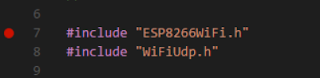
With the alternate 'Tag Parser' the code looks right
More details about the Intellisense engines and setting for C/C++ can be found here:
https://github.com/Microsoft/vscode-cpptools/blob/master/Documentation/LanguageServer/FAQ.md

The issue has been reported on both the VSCode and the C/C++ extension GitHub sites:
https://github.com/Microsoft/vscode/issues/27006
https://github.com/Microsoft/vscode-cpptools/issues/743

==

Adding the NodeMCU and other ESP8266 boards

I don't remember having to do this but I probably did at some point. Add additional boards from the Arduino Board Manager.


Access this from the Command Palette from the View Menu.


Install the boards you require.

==

Tuesday 18 April 2017

Improved Arduino Development Environments for ESP8266

I was going to call this 'alternative' Arduino IDEs but as the Arduino IDE works so well but just lacks a couple of features, I didn't want to rule out an improved Arduino IDE from my list.

Having tried out the Eclipse for Arduino IDE and been hampered by some limitations and known issues, I've decided to quickly try out a few others.

There is no point if the IDE's take too long to install or slow me down in any way.

I'm only after one main extra feature. Call-tips or Intellisense, so I don't have to have the library documentation open in another window, all the time I am coding. Something that displays the available methods and their parameters, as I type, is all I need.

Once you get the call-tips, other features like auto-complete and variable definition checking as I type, so I don't spell variable names incorrectly, usually come along with it.

I like open source, so I'm going to start with free products but I won't rule out low cost paid for ones. I've found a small fee is often worth paying to get a more reliable, less hassle, solution.

I will also rule out products that are not up to date enough to allow new boards to be added easily. It does not matter if the code is a few years old, as long as it was complete and had a feature to easily add boards and libraries.

There are several other sites with lists of things for me to try:
https://www.arduinostarterkits.com/resources/arduino-ide-windows-mac/
https://www.intorobotics.com/alternatives-standard-arduino-ide-one-choose/

In all the examples I have read so far, the IDE relies on the Arduino IDE and any add on libraries being installed on the same machine. This would apply to other language libraries, so is not unexpected.

I will add to this list as I try them.
My testing will be very brief. If it takes time too long to get going it fails the test of saving me time.
My other criterion is that it must work with ESP8266 boards.

//

In no particular order:

Eclipse for Arduino (Sloeber)
Date installed: 17 April 2017
See my more detailed page on this.

Plus:

  • Fully featured IDE
  • Syntax highlighting
  • Call-tips
  • ESP8266 boards included (with v4)

Minus:

  • Projects are not portable (my biggest issue.)
  • Pain to install
  • Does not cope with spaces in path names
  • Does not fully support Windows redirected folders (mainly a nuisance for me.)

The projects not being portable make it difficult to backup work and in my case, difficult to work from different computers.

//

UECIDE
Date installed: 17 April 2017

Plus:
  • Syntax highlighting
Minus:
  • No call-tips that I could find!
  • Failed to compile my example.
I don't think UECIDE deals with nested duplicated #include statements. It probably could be fixed with #include guard statements but that means it is not fully compatible with readily available code examples!

//

Visual Studio Code with Arduino Extension
Date installed: 19 April 2017
See my more detailed page on this.
There are several Arduino extensions available from different authors. So far I have only tried the one from Microsoft.

Plus:

  • Intellisence for call tips and more works very well.
  • Syntax highlighting.
  • ESP8266 included in the board list.
  • Simple, clean interface, fairly easy to use.

Minus:

  • Manual change to a config file to get the ESP8266 libraries working properly.
  • Some of the Arduino specific functions are on a list of add on commands rather than a button.


I will stop here with my installs for now as Visual Studio Code appears to work well and has the features I was looking for.

==

Things I would have tried next...
Visual Studio Community edition with the Visual Micro add-on.

==


Monday 17 April 2017

Defender indicator fix

The indicators stopped working on Fender.

It took no time at all to discover that this was a common problem. The first thing that came to mind was the flasher relay but it appears to be more common for the problem to be the hazard warning switch.


I found a few useful online guides, some of which show the indicator wiring going through the hazard switch:
http://forums.lr4x4.com/topic/25376-hazard-switch-indicators-fault-diagnosis/
http://www.land-rover-blog.co.uk/how-to-fix-a-land-rover-defender-indicator-fault/

It took longer to unscrew the panel to get to the switch than it did to carry out the test and prove it was the hazard switch. Less than 5 minutes to diagnose and a further 10 to re-fit the old, cosmetically damaged, switch, assemble and test all the lights.

A nice quick job for a change.


The cost of the Britpart switch was refunded very quickly by the supplier and I ordered a genuine Lucas part which arrived and I fitted it within a few days.