That light combination means there is an error but not what the fault is. I plugged in the Nanocom to find out.

An electrical fault with the ABS shuttle valve. It did not take long on the Internet to find out that this is a common problem. It can be rectified by replacing the ABS shuttle valve modulator switch assembly (SWO500030). That's a relatively low cost part. Luckily it is also a fairly easy part to replace.
It is even possible without draining the brake fluid, as seen in the linked video. As it didn't need messing with any critical systems it made it a job I was confident at doing.
There are several references on various forums about how the problem is likely to be the internal connector within the block and may re-occur. There is a suggested longer term repair for the ABS modulator switch by extending the wires outside the plastic bit of the switch case to bypass the internal connector.
To save myself a bit of time, I bought a kit where the wires had been extended for me and a connector added.


There is nothing really wrong with the idea of the kit I bought. It is a good choice of connector, an Econoseal, to match other Land Rover connectors and from the same range as the multi-pin connector on the Wabco ABS unit.
The kit is designed so that there is no need to cut any wires nor crimp any pins. Instead two existing leads need to be extracted from the multi-pin plug and re-used in a two pin Econoseal connector. The kit comes with a good set of instruction about how to do that. For those that are not confident with car electrics, this is a good kit.
The bit I am not keen on is that the end result would be that the ABS unit is attached directly in to the wiring loom. In my opinion this could be a nuisance for maintenance in the future should there be a more significant problem with the ABS valve block!
I made a slight variation and cropped off the supplied black wire and spliced it on to the black with grey stripe (pin 8) from the harness.


I taped it up securely as I also did with the now redundant loose end on the modulator switch lead.

The end result is that I only need the two pin connector on the modulator section and the whole ABS block can be more easily removed from the car without reversing the kit wiring installation.

That change meant I only had to remove one wire, the yellow with green stripe (pin 9), from the multi-pin connector.
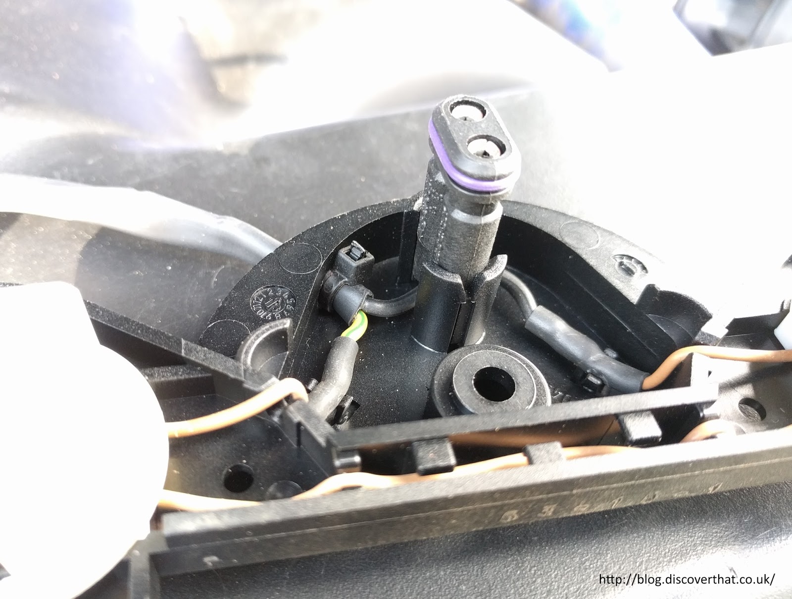
With the electrics all prepped the next job is to get access to the bit that needs replacing under the ABS block.
The three allen bolts under the Wabco unit can be reached if it is lifted out of its mountings. First unclip the brake pipes from the edge of the bulkhead.

Taking off the upper clip from the three pipes routed together, makes it easier to maneuver the block to a workable position.

The block has two 10mm nuts at the back that need to come off however the one at the front only needs to be loosened because it is in a slot. Pulling it up at the front gives enough room to remove the metal cup from the rubber mounting then the whole unit can be pulled forwards to clear the rear bolts from their fixing holes.


You need a 4mm allen key to remove the three bolts to free the valve modulator switch unit. They are very stiff because they have thread lock on. My tiny ratchet made the job a lot quicker.

The old assembly pulls downwards to remove. The connector remained in the block and had to be grabbed separately to get that out.

The new one goes in easily and the supplied new allen bolts go back in. They have fresh thread lock on them.

The block can be bolted back on to the car. The brake pipes can be clipped back on to the bulkhead. The next job is to finish off the electrical connections.

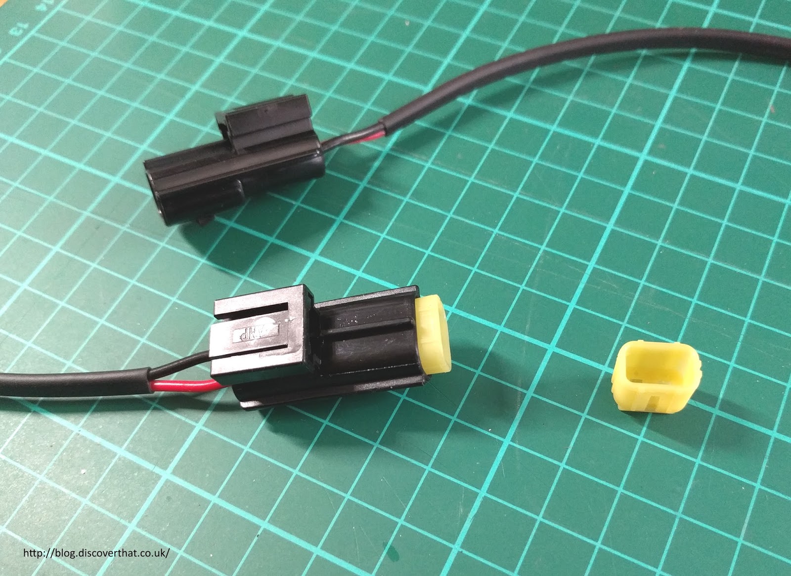
One pin has to be backed out from the multi-pin connector. This is fairly easy with a small watchmakers size screwdriver. Once the yellow shield has been removed you can get the screwdriver in to hold the plastic latch out of the way. The wire pulls out the back.
One comment about the kit I bought. The person who crimped the pin on was not fully familiar with Econoseal connectors. To be fair, it took me a while to find the correct instructions.
 |
| Upper seal, wrong, lower seal (original) correct |
In my opinion, they also used the wrong sized seal for the gauge of wire. I would have used a yellow or brown colour seal which has a larger diameter inner hole.

A little tip. The blanking seal that needs to go in the now vacated pin 9 position, will only go in one way round. As shown in the above photo. Hold the smaller end and push the larger in end.

Assemble the new 2 pin socket and connect it up.

Back inside the car to connect up the Nanocom again.


==
Update: 12 March
It's been two weeks and no sign of any faults.