Search This Blog

Monday, 13 July 2015

Miniature Lawn

Probably more embankments than lawns but several areas of neat grass before I've added the shrubbery.

The photos show it all.

From this...


Several layers of paint...


I have to plan my days work round the paint drying...


Lots of PVA glue and Woodland Scenics scatter grass...


To this.


Tuesday, 7 July 2015

The Hills

The remaining sections of the layout are all scenic. The gaps under roadways become hills and embankments.

The intermediate stage is a bit of a mess, with plaster from the Modrock and patches of rogue filler spread about the place.


I used floral foam as the base because I had lots of it left over. Rough cut and carved to form more natural looking areas. It's just tacked in place using a squeeze of PVA glue.


The Modrock plaster of Paris bandages are very easy to apply. Just a moment in the water and lay in to place over the foam. It's this that holds everything firmly in place.


I left the plaster for over a day to dry.


I used decorators filler over the top. This allows me to shape the hills and adds a lot of strength to the finished mounds. I feather the edges so there is no sign of the Modrock bandage material.


The filler is quite thick in places and will need a few days to dry thoroughly before I can paint it.

The scruffy period will be worth it to get to the finished result.

Monday, 6 July 2015

Underpass

The layout looks like it is nearly all wall at the moment. This is because they need to be in place before I can add some more hills.


I've added a couple of more complicated shaped bits of walling.


One is made from pressing a 3D printed mold in to the floral foam.  That is so easy and takes just a few seconds. I would thoroughly recommend making walls with the foam.


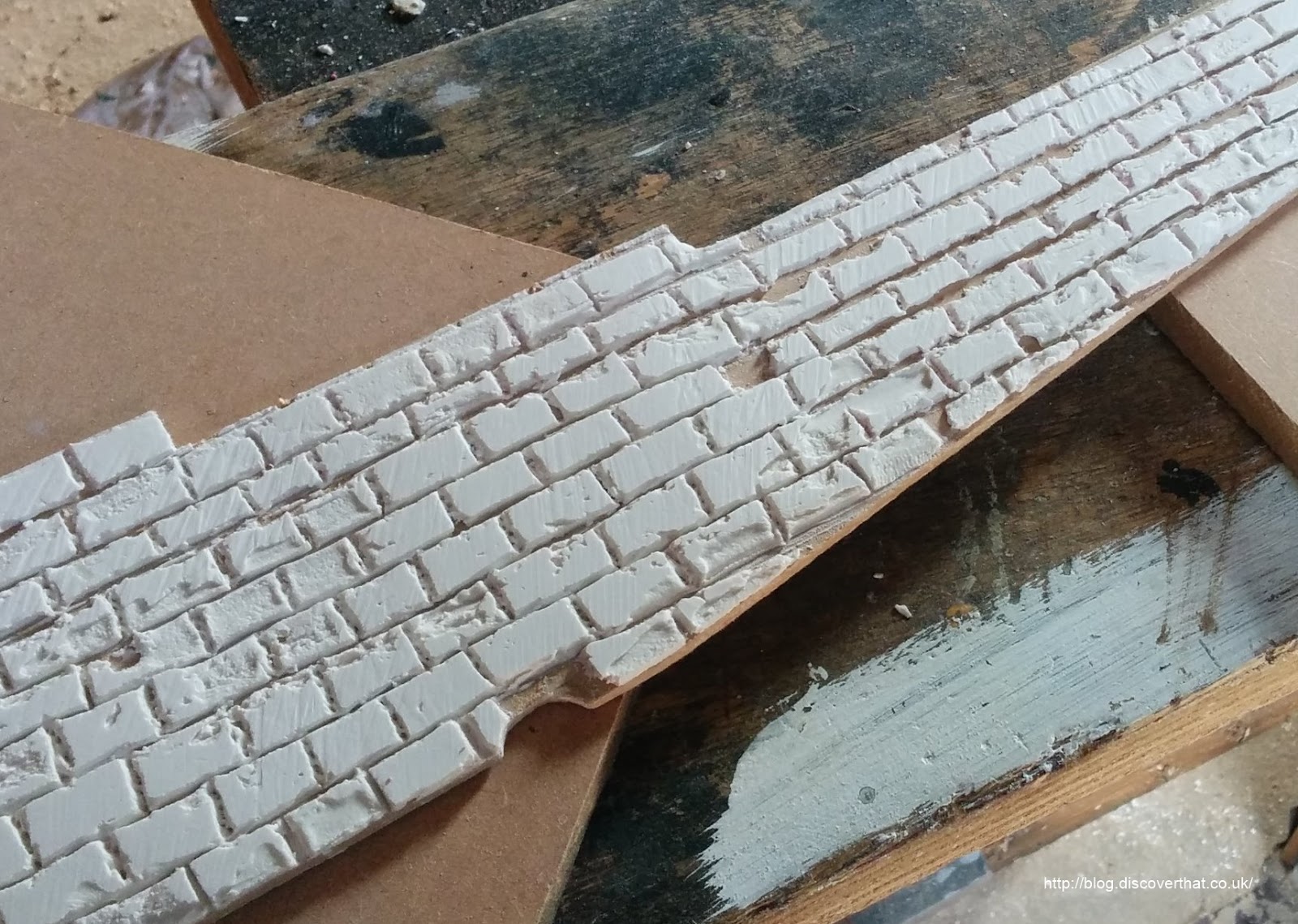
The other, used to make the walls of the long underpass, is made from drawing lines in to a thin layer of decorators filler. I've detailed this in other posts but I would not recommend it. It's only advantage is that I had the materials in my shed. It's difficult keeping it in place while working, it's difficult to make the brick shapes look right, its time consuming patching up the problems when it's dry!


You can see the difficulty with the filler in the above picture. The bigger chunks where you can see through to the MDF all needed to be made good before painting.


I am happy with the end result but I feel there might be other materials that are easier to use to get the same results.


==

The brick wall cookie cutter is available from my designs on YouMagine.com

Sunday, 5 July 2015

Steel Gate

Another 3D print for use on the slot car layout.

A galvanised steel gate model. Something to add a little bit of variation to the scenery.

The detail I could get on the upper surface was better than I expected. To give it some scale, the hinges on the right of the gate in the above image are about 1mm wide. Now look at the catch on the left, the little slot just visible on the lock plate is only about 0.5mm tall.


The side facing the printing bed, shown above, did not come out very neatly no matter what supports or which way I printed it. I'm filling and sanding that side to make it good.


It's just about ready for painting.


Downloads

Blend file
STL file
Licence share alike

==


Monday, 29 June 2015

My Blender preferences

Every time I come back to Blender I forget how I had it setup the last time I used it.

Obviously settings are to each persons' taste but I have never quite got on with all the Blender defaults.  I assume when using a new programme that the authors know better than me what are the best settings for their application. Eventually I give up and use my own choice.

Rotation


The default rotation type of Turntable is fine but it pivots round a hard to understand global point. It almost feels arbitrary to me.

I prefer it to pivot round the centre of the selected items. It's still not ideal every time but at least I can understand what it is doing.


Zoom


This is just my preference. By default Blender zooms to the centre of the current view. Sometimes that is OK but I find it quicker to zoom to where my mouse is pointing.

Metric


I like to work with actual sizes and I like those to be metric.


Ideally millimetres (mm) but although Blender allows entering numbers as mm, it displays the results in centimetres (cm).


I use the scale option to get the result to be mm. One unit size equals 1mm.

I am sure that most readers will assume that my preference for metric is because I have grown up in England. This is not entirely the case. I am old enough that I can work in both imperial and metric and I do still measure in inches when working on less precise jobs, like fences for the fields. When I'm 3D modelling, I typically need some accuracy and millimetres is just so much easier at all scales.

I can't complain because I still prefer working in degrees and not radians but clearly Blender's interface is designed for the units  most commonly used in Europe and not for people like me and most of the building trade in the UK that work in the scientific standard size of millimetres.  I am happy there is a choice and centimetres are much better for my needs than inches.

Display


The information I display while working changes. It is handy to hide bits so they do not get in the way.


The things I find useful are the lengths of selected edges to get accurate sized objects and the normals to show the outside face of a surface.


I also turn on back face culling to help with keeping track of the outside and inside of objects.

As I find other preferences, I'll update this page.

==

Saturday, 20 June 2015

SketchUp to Blender

I have not spent enough time learning SketchUp to be able to create detailed models. I like the idea, it has a free version (for non-commercial use), people can produce some excellent models in it but as I am already familiar with Blender, I tend to want to work in that.


I can produce some basic shapes very quickly in SketchUp but I start to struggle when trying to add very detailed shapes and manipulate existing models.


SketchUp has a huge following that create some excellent models and make them available, many of them licence free, on the SketchUp 3D Warehouse. Once I exhaust what I can do quickly in SketchUp I usually convert them to Blender.


I export them from SketchUp as a Collada (.dae) file which usually Blender can import.

I have had a few problems importing SketchUp files and if necessary I'll install the OBJ exporter available from the Extensions Warehouse. Click on the icon in SketchUp to open the Extension Warehouse and search for OBJ.


It is intended to work with SketchUp 2014 but I found it also worked with SketchUp 2015. A bit clunky but it worked to get the tricky models in to Blender in OBJ format.


At the Blender end it may be necessary to adjust the rotation to get the model upright. Usually +Z Up is the correct selection.

Wednesday, 17 June 2015

Road bridge railings

I have now used the 3D printer to create a scenery component for my Scalextric layout :-)


Where the Scalextric track crosses a bridge I wanted to have as much visibility as possible.

A stone wall would have looked nice but it would block out the view.  It would also be impractical in the real world because there would not be enough height to have a stone arch to support the span. Although the layout does not have to be realistic the scenery always looks better to me if it could exist and support itself in the full size world.


I decided to opt for a modern bridge style with an implied concrete and steel support structure and the thin metal railings being the only thing on show.

The railings are very easy to look through, which is what I wanted. The drivers can still see the curve of the lower level road just before the cars go under the bridge.

I could have made them from odds and ends but I now have a 3D printer so this was a chance to try something out.


The design was fairly easy to work out. Created in Blender, as usual.


I made minor changes to the design to suit 3D printing. The fronts of all the rails are level with each other. This allowed them all to lay flat on the bed for printing.

The first attempt at printing was a failure because, even though I had positioned the barrier on its front, the posts still overhung in mid-air.


I re-imported the model and selected the option to print support structures, for the second attempt. These are finely printed extra bits automatically added by the Cura software to support overhangs.


This worked very well but obviously requires a little bit more cleaning up afterwards.


Some of the details are a bit fine for the normal print quality. This took just under 2 hours. If I wanted to fix that I could either thicken up the fine edges or print using the fine or ultra fine modes but that would take a lot longer to print.

TIP: A thickness of 1mm is too fine to guarantee to print using the normal detail level. 2mm thickness prints out perfectly on the normal quality level so somewhere between 1mm and 2mm is the smallest detail for this setting.


I was very impressed by how easy the automatic support structures were to remove from the finished print.


In place on the track, the railings look exactly as I intended.


Another success.


Downloads

Blend file
STL file
Licence share alike

==