This is supposed to be a quick reference to make it easier for me the next time I set up the software.
These notes assume the default screen layout and colours. I am sure I will reconfigure this at some point in the future.
Axes
I started with the pins and ports for the Pulse, Dir and Enable lines.
I use active high. In the case of the step pulse, this means that the pulse activates on the rising edge not the falling edge of the pulse, therefore there is no tick required in the 'active low' check box.
The pins and port numbers come from the breakout board.
Enable Line
I have the enable line connected, in that case I had to activate the enable pin on all three axes, otherwise nothing moved. Active high.
Speed and Calibration
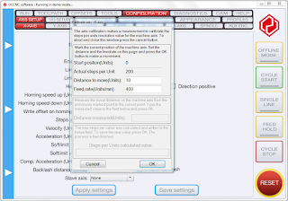
I was expecting this to be more difficult but the built in calibration routine made it very easy.
The software calculates the 'Steps per unit' based on the measurement of a known distance.
I work exclusively in millimetres (mm) so for me, one unit = 1mm.
I just pressed the calibration button and followed the instructions. In short that was, measure the distance travelled in, my case, millimetres, enter that back in when requested and the correct value is calculated.
I ran this a couple of times to get a more precise result.
I also adjusted the velocity to something I was comfortable with. For a cutter the velocity would need to based on the material being worked on but for the pen I am using for testing, a rough guess is acceptable.
Soft Limits
These look like they will be useful for my proof of concept machine because I do not have any physical limit switches. I have not tried these settings out yet.
I/O Setup
There are lots of optional settings on this page but I only use the emergency stop (E-stop).
My E-stop is connected to pin 10, and this is normally ground when the machine is OK to run. It is therefore, active when it is not low, which is high or technically floating, as far as I know.
Lining up the tool head with the UCCNC software
I followed some online tutorials and started with the Z axis to avoid crashing that on the bed.
I used a piece of paper resting on the bed or it could have been the work piece. I jogged the head down until the paper was just gripped by the tool.
I then zeroed the position in UCCNC using the pale blue button next to the axis.
I raised the head, a little, to avoid it fouling the work piece.
 |
| Image from an older software version [to be replaced with a newer version] |
I moved the tool X and Y positions to move the tool to a position that corresponds with the tool position indicated on the tool path view.
I was looking at the machine upside down, so from my view the pen needed to be in the far right corner. That corresponded to the lower left corner on the tool path view.
I don't know if that orientation is normal for CNC machines, but it would be correct if I was peering over the top of the gantry from, what I call, the back of the machine.
Once the screen view and the physical tool were in corresponding positions, I zeroed the X and Y positions using the pale blue buttons within UCCNC.
For me, that had aligned the tool head on screen with the real world position of the tool.
UCCNC was ready to use.
Xbox 360 controller
The Xbox controller is a very popular addition as a hand held jog control tool. It's a lower cost than the professional dedicated units and very effective.
The add-in for using an Xbox 360 controller is included with the UCCNC software installation and there is a description file within the UCCNC folder for what codes to use for each function.
I followed the instructions to enable and configure the plugin.
It's on the Configuration, General Settings tab.
After ticking the Enable button for the Xbox 360 plugin, it was necessary to close UCCNC and restart it.
I used the Show button to configure the controller buttons.
I have changed what all the buttons do. My preferences are:
- The Z axis controlled by the bumpers.
- The X and Y axes controlled by the left stick.
- The jog speed is changed using the controller X and Y buttons
- The movement speed is controlled by the controller A and B buttons
- Cycle start uses the controller Start button
- Cycle stop uses the controller Back button.
Much more convenient using the Xbox controller to move the tool about. A bargain for less than £15.
==
Links:
The video for the Stepcraft Machine Setup, shows aligning the tool before starting work.
https://stoneycnc.co.uk/uccnc-software/
Setting up an Xbox 360 controller.
https://www.youtube.com/watch?v=ve-HJjnXvog
==
Shapecut Series:
Part 1 - Magic Eye to CNC
Part 2 - CNC proof of concept design
Part 3 - CNC controller enclosure
==


No comments :
Post a Comment