Search This Blog

Sunday, 23 January 2022

Defender interior lamp connector

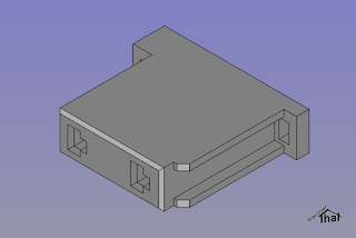
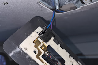
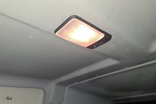
In the process of fitting the rear headlining and specifically a lamp in the rear, I could not find anywhere to get the connector that fits the standard Defender light fitting. They have, in the past, been available on ebay, but not when I was looking. My solution, as usual, was to design and 3D print one.
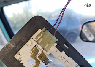
Original Part

I believe that the connector is part number AMR3158.
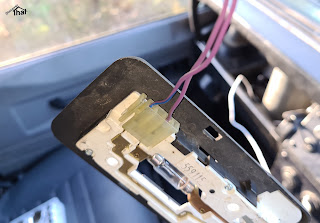
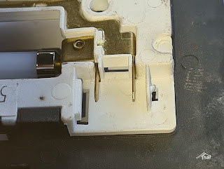
Factory fitted connector


It is connector C357 in the 1997 electrical circuit diagram.


Luckily, the spades fit perfectly into the commonly available 2.8mm connector pins. The 2.8mm connector housings that are readily available online, have narrower spacing between the pins.
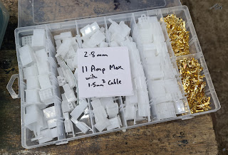
Readily available 2.8mm connectors


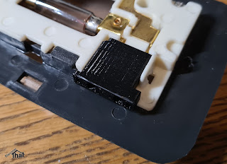
I designed a housing with spacing to fit the lamp, using the 2.8mm pins that I already had. The light only uses two pins 10mm apart.

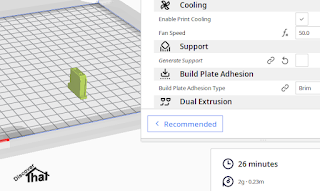
Just off the printer

Snug fit

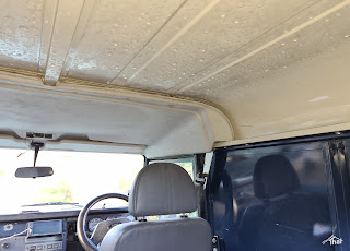
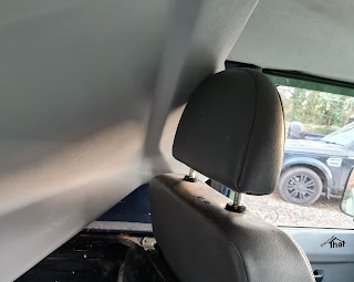
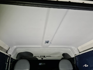
The bare roof and condensation

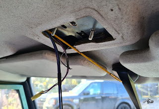
Threading to the front light

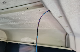
Pulled cables through to the rear

I threaded the cables above the front headlining prior to fitting the rear.

Honestly, it does fit... 

... just about. Needs manoeuvering


This was intended to be an article about the lamp connector but I'll mention fitting the headlining, while I'm here.

The headlining that I fitted was purchased from Simmonites. It's a thin fibreglass panel.

There are a number of trim clips holding up the headlining. I measured the one central trim clip from the centre of the row of trim clips between the front and rear sections. That avoids the risk of movement while measuring. I then marked the row of trim clip holes by offering up the two halves and visually looking at the centres. They were 15mm from the edge and I drilled 8mm holes.


I cut the hole for the lamp holder using a rotary tool and drilled a small hole in the centre spar to secure the bracket.


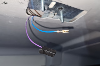
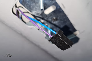
There are three wires, spliced in to the same cables from the front light.

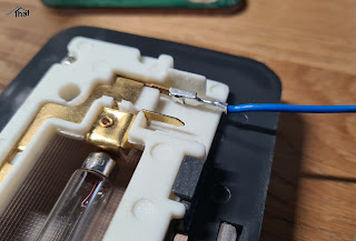
The purple wire is a permanent live. I had purple 0.5mm2 cable available, so it matches the original. The correct method is to disconnect the battery but, of course, I just took care not to touch anything while fitting the crimp. I was happy when the end of the purple cable was safe in the housing.

I had blue 0.5mm2 cable available, so I connected that to the purple/blue cable of the original lamp. It's an earth via the immobiliser ECU. 

There is also a black earth cable, using a 6.3mm spade connector, plugged into a tag cut into the bracket. The bolts are the earth for the lamp.


The connector was a tight fit but worked.


Download:

Connector C357 AMR3158 STEP and STL (Zip)


==


Saturday, 8 January 2022

Using TDCi switches in a 300TDi

In the process of personalising Fender, I've fitted newer switches. That requires a few wiring changes.


The linked PDF document details the necessary connections for the main switches and the changes to use a TD5 or TDCi (Puma) engine tail door harness instead of a 300TDi harness:

300TDi to TDCi connectors (PDF)


Switch Mounting

I have also designed and 3D printed various panels to mount the newer switches into a 300TDi.


We have a Raptor Engineering centre dash that I had already configured to fit a specific Sony Stereo. I changed one section to fit the switches. The panel cut out is for a single DIN radio. All the switch mounting panels are in the same style as the Raptor dash.


On the drivers side the hazard and rear fog switches will just fit into the space of the original small  switch panel.


Downloads:


DIN button panel STL and STEP (Zip)

This is two parts. The three M5 bolts clamp the two halves together.


Small button panel STL and STEP (Zip)

This is three parts. The thin rear walls can be superglued in to place or just left free to be held in place by the switches. The middle hole is for a cosmetic self taping screw to match the mounting screws at either end.


TD5 and TDCi button blank STL and STEP (Zip)

I print this with 1.2mm thick walls standing on the button face. I have to sand it down and paint the part that is on show.


==


Friday, 7 January 2022

Fender is back

When Shelley's previous Defender, Fender, was written off, its remains were bought by the owner of the garage we use.


Much to our surprise he rebuilt it much quicker than we expected and we asked for first refusal if he was ever to sell it. He did and we bought it back at the end of November.


Mark at Gratech 4x4 has done an excellent job getting Fender back on the road.

Since then I've been personalising it and putting back the electrics needed now that it is a van again.


Running the wires for the tail door central locking.


I've re-enabled the central locking and added the solenoid and linkage to the tail door.


As the tail door was from a TDCi Puma, rather than the older 300TDi, I've had to change the connectors and some wiring to suit.


I've replaced all the old switches with those from newer Land Rovers, mainly the type from a late TD5 or TDCi. I've had to swap over several connectors, mainly for the switches. I chose to try to keep as close to the newer model wiring, so I've put new connectors on the old 300TDi wires to match the TDCi door wiring.


I've 3D printed bits for the dash to fit the newer switches.


Plus there are some more jobs on-going.


==


Wednesday, 29 December 2021

VW Transporter T5 ignition feed for a radio

The radio wiring in the VW T5 and T28, at least for the 2008 model year, does not have an ignition switched live feed. 

It's easy enough to buy an adapter from the Quadlock plug to the standard ISO connectors, but they will have one or two wires not connected to anything. One is for power on and the other is for the illumination.  The simplest, and an acceptable, solution is to connect them both to an ignition live feed.

From what I can find on the internet, there are a couple of places to get this feed. 

A possible location is the Anti-Slip Regulation (ASR) switch, which is usually near the radio. The trouble is, I could not find any details of the wiring, so I do not know what current rating the feed has, nor what fuse it is attached to. I could have tested the wires to determine which to use but I'd rather a known quantity.

The other suggested option is Fuse 19, which I prefer. 

Fuse 19 

This is Fuse 19 in the top fuse box. That is designated for, among other things, radio and navigation systems. It is a mini 5A fuse. 


To get to the wire, it is necessary to remove the passenger side dash panels. This is a few screws and a couple of pull off panels. An easy job but takes a few minutes. 


Once the panels are removed, the top fuse box can be unbolted and I found there was just enough slack, that with a little care, I could slide it out sideways and have good access to the rear cabling. 

Fuse 19 is one of the tiny fuses in the middle. 4th in from the right. The feed comes in, from the ignition, on a brown/green wire and exits on a brown/red wire. 

I spliced into the brown/red wire. 


==

Other similar articles:

https://audiotechdirect.com/blog/vw-transporter-t5-stereos-installation/

==


Monday, 4 October 2021

Defender Puma heated seat electrics

We already had the Exmore Trim heated seat elements in the seats in Shelley's car. I wanted to wire them in using the original Land Rover switches.


It was easy to find a set of switches on ebay with the connectors. I'm not keen on them being pre-wired but that's how they came. Land Rover's standard wiring has the heating element controlled directly by the switch. I was unable to find out the current limit of the switches, nor the current draw of the Exmore Trim heating elements. All I know is that they use a 20A fuse for the pair.

It is safe to assumed, that the seats draw less than 10A per seat. I didn't want to take any chances with the Land Rover switches, so I have run them to relays.

The above is the updated circuit diagram with the heated seat switches connected via fuse 33. I also ran cables ready for a Sub-Woofer. The positive feed is shown in the above diagram, connected via fuse 32.


I was able to buy the contact pins that fit the standard Land Rover fuse boards, so I was able to use two of the spare ways in the under dash fusebox, to fit the fuse for the heated seat switch feed and another for the sub-woofer power. Both are switched from, what is called, the Window relay. That relay feeding various things, like electric windows and heated seats, when fitted, plus the windscreen wipers.

It's a bit tricky to access the fusebox because, although it can be unbolted, it does not fit through the opening in the dash. I managed to do what I needed.

I had a bit of luck with the feed for the power to the seats. There is an unused fuse in the under seat fusebox. Fuse 4. I happened to have the right spade connected to add in to the plug in that fusebox to connect to Fuse 4 and that fuse is marked as 20A. Perfect for my needs.


I ran a wire from the under bonnet ground stud to an unused stud under the seat. That probably wasn't necessary but with a definite negative connection to the under seat point, I was confident using that for all the negative connections.


I made up some harnesses and threaded them out in to the engine bay and under the car to the UK drivers side seat box. In that box are the two relays. They are attached to the relay brackets handily provided by Land Rover. From there another cable runs to the UK passenger side seat box.


It's just a job of terminating all the wires and plugging them together.

==