Search This Blog

Saturday, 4 January 2020

Bike steerer tube bung

This was requested by Dean to stop the grub and water filling up the steerer tube while cleaning the bike. He's used various things in the past but with the power of a 3D printer and some design work using Fusion 360, I came up with something that fits tightly.


This is not intended to stay in place while riding. In fact I would think that keeping it in place would trap moisture and encourage corrosion. If you are looking for something to keep the mud out while riding, I would suggest some air filter foam stuffed up the tube. That will keep the mud out and allow any moisture to evaporate.

The bung is designed to be pushed in to a tapered fork stem. It just pushes up, just inside the steerer tube, and holds in place while the bike is being cleaned. Best to clean out the tube with a rag before inserting the bung.


Despite taking lots of measurements from three bikes, the end result needed trial and error to get the bung to sit just inside the tube. If it goes too far in, it leaves too much tube to fill up with water and it is difficult to reach to pull back out.


They need a loop of strong string to help get it back out.

The differences in the diameter between an SR Suntour, Fox and Rockshox forks were only about a millimetre in total between the three. I still had to make them to fit specific forks. Only 0.5mm diameter difference between each!


Of the forks I have tried, the smaller fits the Suntour, the medium fits the Rockshox and the larger fits the Fox. I modelled them with a dot in a different location on the handle, to help identify which is which.


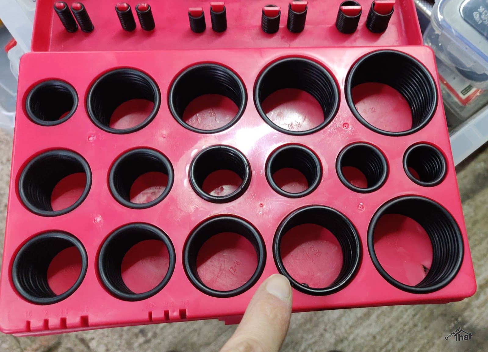
They all use two metric rubber o-rings. An o-ring with an inside diameter (ID) of 25mm and cross sectional diameter of 3.5mm fits all of them. I would guess that imperial o-rings with ID 1" and cross section of 1/8" would work just as well.


They 3D print as two halves with two alignment keys. I printed it all without any supports and just a skirt. It needed no cleaning up and can be pushed together. It's a tight fit. I also used a dab of superglued (CA) but that is not essential.


==

Download 3D models:
Steerer bungs, Fusion 360, STEP and STL (Zip)
Licence attribution - small business exception

==

Wednesday, 25 December 2019

Derailleur front mount cover

On bikes that ship without the front derailleur but with the welded on mount, they usually have a blanking cover on the bracket.


Typically a plastic tile or even an aluminium shaped billet. Easy enough to buy but also very easy to model and 3D print.


I've created some custom ones.

3D printed.


I filled the letters with Milliput and sprayed with clear lacquer.


==

25.4mm wide, 26.5mm tall, 4.6mm thick, 2mm radius corners. 5mm wide x 2.2mm deep keyway on the back. Fit using an M6x10mm or M6x12mm countersunk screw.

==

Sunday, 15 December 2019

Fitting dropper posts

This weekend I fitted two dropper posts.  One was the old Rockshox Reverb that Roy and I had serviced a couple of months ago, fitted to Roy's Whyte. The other was a new Rockshox Reverb Stealth (B1) fitted to my Giant Stance.

Internal Hose Routing

There are plenty of videos showing how to fit dropper posts, so I'm not going to repeat those excellent tutorials, however, what many of them assume is that you are replacing an existing dropper.
https://www.youtube.com/watch?v=f1__XVOjkvo
https://www.youtube.com/watch?v=4Ei6GlmPlAo


I was threading a hose through the frame of a bike that had not had a dropper before. That makes getting the hose in place a whole lot more difficult. The reason I chose the Rockshox over other makes was because, apparently, the hydraulic solution is more tolerant of tight bends. I'm glad I did.

I thought I might be able to use the cable threading fishing tape and rods, that I already have, to get the hose in without removing the bottom bracket from the frame. I was wrong, the local bike shop was right! I had to remove the bottom bracket.


The bottom bracket is a SRAM DUB pressfit and I found a couple of videos showing how to remove and install similar.
https://www.youtube.com/watch?v=yOJAKBQOU9U
https://www.youtube.com/watch?v=E0CDaxwbd5c


Luckily, one of the many articles I looked at mentioned to watch out for the spacer (4.5mm) on the right hand, chain-ring, side. It would have been very easy to miss that. It just pulls off or drops off while you are not looking and rolls under the work bench!


I was glad I had bought a drifting tool designed to remove push fit bottom brackets. Without that I don't think there was any chance I would have got the job done. I only bought a budget tool from Amazon. It needed the splines bent out a fraction but worked fine. I needed to use a lot more force than I was comfortable with but the job needed to be done.

I'm pretty sure that drifting out the bearing housing from the frame is very likely to have misshapen the bearings. They still run, just, but if I was doing it again, I would have bought a new bottom bracket, rather than re-use the one I took out. A new bottom bracket is on order.


Tips:

  • The right hand end of the inner sleeve of the SRAM dub pressfit bracket is fixed to the bearing cup. The left hand cup slides along the tube with a fine washer to seal the gap. That allows the same component to be used for both 89.5mm and 92mm shell widths. (SRAM part number 00.6418.016.000)
  • With the SRAM dub pressfit, it is only necessary to remove the RIGHT hand, chain ring, bearing, along with the inner sleeve, to be able to thread the dropper hose.


I wasted a fair bit of time trying to fish through the frame. Once I had the bottom bracket out, I could see that was never going to work.


There are flanges, lips, where the tubes join. It was hard enough getting past the flanges when I could fish in there from both ends.


With the hose routed, the rest of the jobs were relatively easy. The bearing press I had ordered had not arrived, so I used a long M14 bolt with some big washers, which I had to hand.


It needed some care to ensure it was pushing in straight but the nuts, bolt and washers, worked perfectly as a bearing press.

Everything else was as per the SRAM video.


Sanding the inside of the top tube, using friction paste, torquing up the saddle stem, adjusting the length of the hose for the handlebar remote and fitting the remote.


Not forgetting to slide on the grommet before attaching the remote.


Finally fitting the saddle. By which time it was late and very dark, so I test rode it the following day.

==

External Hose


That next day, I fitted the externally routed hose on my brother's bike. That was much easier.


I 3D printed some hose guides so that it did not touch the tyre or anything else when in the dropped position. It needed two guides but they worked well.


As an extra job I tried to adjust the front derailleur because initially it would not move up or down a gear. Again I followed an excellent video.
https://www.youtube.com/watch?v=ZNG7g83lI-s&t=51s


Although I have managed to get it working, it is not very positive. I'm fairly confident that too many of the components, including the chain-rings are just too worn.


As a side note, I found a way to stop the rubber ends falling off my work stand clamp. As simple as a couple of cable ties!


Roy's Whyte is now in a rideable condition and my Giant has a nice new dropper post, ready for those steep hills.

==

Download 3D models:
Dropper Tube Guide, STEP, Fusion 360 and STL files (Zip)
Licence attribution - small business exception


==


Saturday, 7 December 2019

Sources of components for 3D models

When creating models, quite frequently, I use standard, nuts, bolts, extrusions, motors etc., even linear rails and other more complex, off the shelf parts. 3D models of many of these are often available from the manufacturers but it can be difficult to find or even to know which manufacturers provide 3D models that are suitable to include in my own designs.

3DContentCentral.com

The following are sources I use to look for pre-built 3D models of components:
https://www.3dcontentcentral.com - many suppliers include their models on this site. Available in numerous file formats.
https://www.mcmaster.com - this vendor has all sorts of fixing, nuts, bolts, threaded rod and many, many more. Their site is also included under the insert menu in Fusion 360.
https://grabcad.com/library - this tends to be individuals who upload their own designs.


==


Sunday, 3 November 2019

Fox CTD Remote 2014-2015

In the process of removing the Climb, Trail, Descend (CTD) remote level from Shelley's bike, I am fairly sure that I have worked out why it did not work very well. For the avoidance of doubt, this is for the remote used for Fox Evolution forks and rear shocks for model years around 2014 to 2015. That remote has long since been superseded.


Shelley did not use the remote and it was getting in the way on her handlebars. It would have been removed, even if it had worked reliably.


The otherwise good instructions for setting up the cables are not clear about some essential requirements.
The main bit, that needs better clarification, is that the CTD shock control knob and the forks topcap, need to be pre-loaded. By that, I mean that the knob needs to be rotated so that the cable is tightened up with the spring tension pulling on the cable.


On both the forks and the shock, this means the pale blue topcap and control knob have to be rotated nearly a quarter turn before the spring tension is felt. It is that tension that returns the remote lever to it's open position.

The above is easy, when you know how. Unfortunately, in my opinion, there is a design flaw with the remote operation when the remote is used for the dual setup of forks and rear shock. The through cable goes to the rear shock but the red rebound control, on the rear shock, tightens the blue CTD control knob so that the spring tension is reduced or completely locked out.


If too much rebound control is applied, deliberately or accidentally, the remote lever will never return to the open position, so both the rear shock and forks do not return to their open positions!


The photo from the instructions, shown above, makes it obvious where Fox expect the cables to go. I have not tried it but in my opinion, the remote might work better if the through cable, clamped with the grub screw, went to the front forks. The opposite of what is shown in that photo.

==