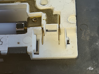
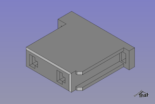
In the process of fitting the rear headlining and specifically a lamp in the rear, I could not find anywhere to get the connector that fits the standard Defender light fitting. They have, in the past, been available on ebay, but not when I was looking. My solution, as usual, was to design and 3D print one.
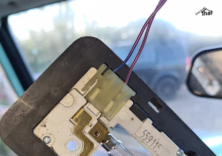 |
| Original Part |
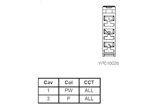
I believe that the connector is part number AMR3158.
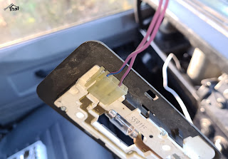 |
| Factory fitted connector |
It is connector C357 in the 1997 electrical circuit diagram.
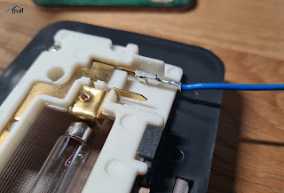
Luckily, the spades fit perfectly into the commonly available 2.8mm connector pins. The 2.8mm connector housings that are readily available online, have narrower spacing between the pins.
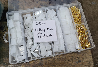 |
| Readily available 2.8mm connectors |
I designed a housing with spacing to fit the lamp, using the 2.8mm pins that I already had. The light only uses two pins 10mm apart.
 |
| Just off the printer |
 |
| Snug fit |
 |
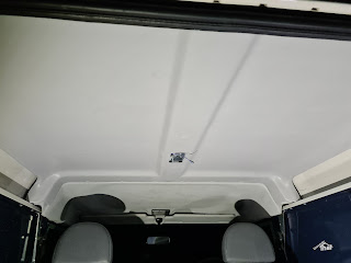
| The bare roof and condensation |
 |
| Threading to the front light |
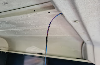 |
| Pulled cables through to the rear |
I threaded the cables above the front headlining prior to fitting the rear.
 |
| Honestly, it does fit... |
 |
| ... just about. Needs manoeuvering |
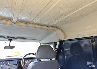
This was intended to be an article about the lamp connector but I'll mention fitting the headlining, while I'm here.
There are a number of trim clips holding up the headlining. I measured the one central trim clip from the centre of the row of trim clips between the front and rear sections. That avoids the risk of movement while measuring. I then marked the row of trim clip holes by offering up the two halves and visually looking at the centres. They were 15mm from the edge and I drilled 8mm holes.
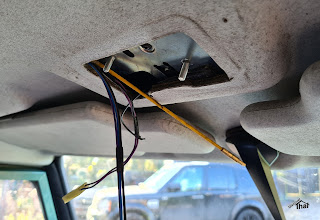
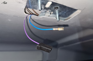
I cut the hole for the lamp holder using a rotary tool and drilled a small hole in the centre spar to secure the bracket.
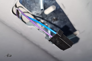
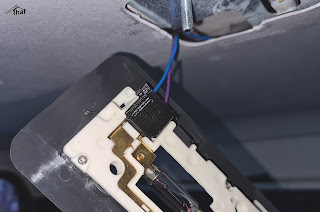
There are three wires, spliced in to the same cables from the front light.
The purple wire is a permanent live. I had purple 0.5mm2 cable available, so it matches the original. The correct method is to disconnect the battery but, of course, I just took care not to touch anything while fitting the crimp. I was happy when the end of the purple cable was safe in the housing.
I had blue 0.5mm2 cable available, so I connected that to the purple/blue cable of the original lamp. It's an earth via the immobiliser ECU.
There is also a black earth cable, using a 6.3mm spade connector, plugged into a tag cut into the bracket. The bolts are the earth for the lamp.
The connector was a tight fit but worked.
Download:
Connector C357 AMR3158 STEP and STL (Zip)
==
No comments :
Post a Comment