
I didn't get as fine control as I would have liked. Deviating too much in any direction prevented the profile from forming a body however I was able to get fairly close to what I wanted.
There were a few tips I needed to know:
1. Project a sketch on to a surface to form the path for the sweep.
2. Create the profile sketch close to the path.
3. Create the Sweep as a PATCH.
4. Fill the ends using Create - Patch, not Modify, to form the finished body.
That's not all of it but they are the bits that were not intuitive to me.
1. The Path
- Add an offset plane roughly parallel to the main surface that the path will be projected on to.
- Create a sketch on that plane.
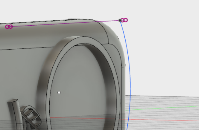
- Draw a line.
- Stop the sketch, the next stage creates an additional sketch.

Select 'Project to Surface' from the Sketch menu.
- Select all the surfaces you want to project on to.
The projected line will stop if any face it projects on to is missing.

- Select the line from the sketch.
- OK.
You should now have a line following the surface of your model.
2. The Profile
Create an offset plane at roughly the top of your path. Perpendicular to that line.
Create a new sketch from that plane.
- Draw the profile you desire at roughly where you want it to protrude from the surface.

If the profile is too far from the surface, the end result may double back on itself instead of following the surface as intended.

If the profile is too far from the path it is likely to cause errors and not allow the Sweep to create at all!
Update: I've done this several times now with different models and by far the most reliable way is to draw the profile on the line of the path.
3. The Sweep
I tried lots of times to create a sweep in MODEL mode but I kept getting an error about it overlapping itself or being an illegal result.
Swap to PATCH mode and it becomes obvious that it creates a hollow tube so the result is never a valid body!
In PATCH mode.

Select Create - Sweep.
- Select the profile.

- Select the path that follows the surface.
- OK.
You should have a hollow shape in the profile you have designed following the surface. If it does not you might find adjusting the position of the sketch of the profile may help.
Do not expect the shape to be exactly where you want it. That can be adjusted later when you have the finished body.
4. Create a solid body
To turn the patch into a solid body it is necessary to fill the ends.

Still in PATCH mode, use Create - Patch
'Patch' is on the Create menu not, as I expected, on the Modify menu!
- Select the end edges.

That should put a face across the end.
Do the same at the other end.
Now make it in to a solid body.
Select Modify - Stitch.

- Select all the patch pieces.
- New Body

You should have a new solid body and the patch parts have disappeared from the browser.
You can now go back to MODEL mode.
In that mode move the new body to the exact position desired.
No comments :
Post a Comment