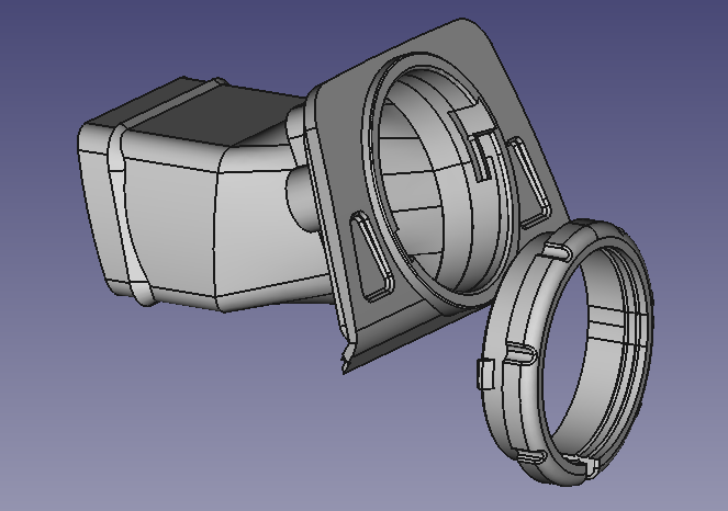
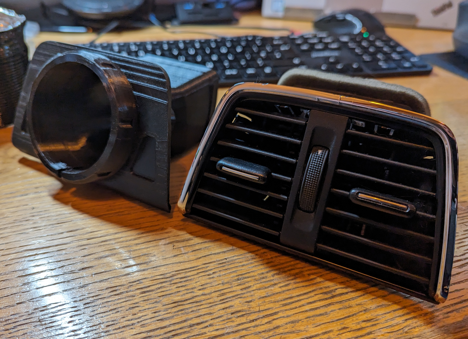
I'm in the process of creating a somewhat awkward shape. It is to fit in the space of a vent in a car. There is not a single square angle on it to use as a starting point for measurements.
Positioning Sketches
Did you know that you can move and angle a sketch. It's a very handy feature.
As several of the edges are not square to anything, I have picked an arbitrary horizontal. This roughly equates to how the original vent sits on a table. To draw some of the surfaces, I have drawn them all on a flat plane and then repositioned the sketches so they all rest on the same point and at the same angle.
That is an example of a sketch at an angle. It's hard to show on a 2D image.
Selecting the ellipsis (...) at the end of the Map Mode property for the sketch, brings up a dialogue panel to change the position of the sketch.
This is the dialogue box I used to get the sketch in that position. It's worth noting that the directions and angles are all relative to which plane was originally selected as the base for the sketch. That means the Z direction is always along the normal vector out of the drawing.
Using the Part Design workbench, I have copied and pasted many of the sketches to use as the basis for other sketches, or even to position at different distances to form symmetrical shapes. When the sketch is copied it retains the position of the copied sketch.
When the copy dialogue appears I have found it necessary to unselect the original plane, otherwise I end up with lots of duplicate standard planes.
Hidden Object Errors
I don't get this very often but it can be confusing. Sometimes a sketch will just not work as a pad or a pocket. Refusing to compute.
In the case I have in mind, I luckily remembered that when I had tried to create one circle, nothing had appeared and I had to repeat the process. What I know now is that the circle had been created with a zero radius!
I found it by going into the sketch and selecting each circle element in turn to see which one did not change colour. I deleted the rogue circle from the list of elements. In this case, I also had to recreate some of the conditions and I was back to a working sketch.
[FreeCAD: 0.21.0]
Download:
STL and STEP format vent model (Zip)
==


No comments :
Post a Comment