
I wanted something like a baby monitor for the cars. If anyone approaches or tries to remove a car, we get notified. Most alarm systems are expensive and tend to use GSM signals to send notifications to mobile phones. We don't have any mobile coverage at home so I wanted something that uses WiFi and the Internet. I could not find anything off the shelf, hence why I've built this.

I'm using Pushover to send push notifications to an app running on our phones. I also have a receiver for use in the house. That's still on a breadboard while I design a housing for it.


The design is fairly simple. If the normally closed switch, on the alarm sensor, is open the NodeMCU sends a push notification to mobile phones and sends network messages to any receivers on the network. There's handshaking at startup to notify all the receivers so they can monitor for tampering.
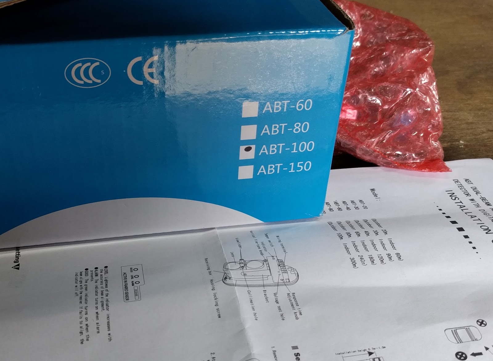
To protect the driveway I've opted for IR beams. I bought a pair of 100m range beams from ebay that accept a big range of input voltages. Anywhere between about 11Volts and 24Volts. I had a handy 12V adapter. I'm using an OKI-78SR voltage regulator. The OKI-78SR-5/1.5-W36-C I selected accepts any input voltage between 7V and 36V and drops it down to 5V which I then connect to the Vin on the NodeMCU. That way the one 12V adapter powers both the IR beams and the NodeMCU.


Both ends need power so we had to dig a trench across the drive and lay a cable. I used exterior mains cable to reduce the voltage loss. I only need two wires because my code deals with detecting tampering.

As the power is low voltage we only dug a shallow trench. One cat deep by one cat wide :-)

It was hard going as confirmed by my mattock!

I did manage to straighten it.

The wooden shuttering in the photo's is to protect the cables from the bites of horses.


The beams need to be aligned for them to work. It was easy when I tried it in the study but it was a bit fiddly in the driveway.

There's supposed to be a way to do it with a built in periscope type device but I could not work out how to use that so I did it by eye. There's a level light that gets brighter as the beams get near to alignment. You can use a voltmeter to get a more accurate setup but it works well enough without going to that degree.


I soldered the NodeMCU to a small piece of stripboard. 13x15 holes. With hindsight I should have aligned the NodeMCU to one side and used jumper wires for the LED. That would have made the voltage regulator fit better. Despite that, my layout does fit in the housing of the beam receiver, so it's OK as it is.
I used some hot glue to hold the fly leads securely under the nodeMCU. I connected the 12V socket outside the IR beam housing to minimise the wires inside. That gave me just enough space for my NodeMCU board.

All connected up, that's it.

Now every time anyone crosses the beams we get notified.
==
Bill of materials
Trigger end:
- NodeMCU (US$3.50 from China, £8.50 from the UK)
- LED (optional, about £1 for lots)
- Stripboard (£1.50 for a bit larger than needed)
- IR beam alarm (£26 from ebay)
- Cable to connect between the beam ends (£30 for 50m from ebay)
- 5V voltage regulator OKI-78SR-5/1.5-W36-C (£3 from RS Components)

Receiver end (optional):
- NodeMCU (US$3.50 from China, £8.50 from the UK)
- Red LED
- Green LED
- Passive buzzer module (£3 from the UK or less from China)

==
Download:
Alarm trigger and receiver code (zip, Arduino C)
==
No comments :
Post a Comment