Wednesday, 27 April 2016

Lawnmower starting handle

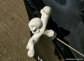
When the pull cord handle on Shelley's lawnmower broke I made this as a replacement:


The pull cord passes up the handle, round and out in the bone under the skull. To be knotted then pulled back and hidden in the cross bone.


Here is the handle in design and production:


Shelley found it very comfortable to use.


Pimp My Lawnmowers


Once I'd started I had to go a bit further. I made a stencil and added some skulls to the little lawnmower and the bigger sit on mower :-)


Downloads:
WARNING: Pull starting engines can be dangerous. There is a risk that the handle can be pulled out of your hand so fast that it breaks bones. Always read the instructions. Do not use this replacement unless you are confident that you know how to use the equipment you are attaching it to. You use this entirely at your own risk.

Skull handle Blend file
Skull handle STL file
Skull handle licence share alike


Updated May 2016, August 2016, April 2017 and again June 2017. This version is hopefully stronger. The earlier ones cracked in two places when the pull handle hit the lawn mower metal tube.

Printer settings (updated August 2017):
Ultimaker 2+
Filament = 14m
Layer thickness = 0.15mm with 0.4mm nozzle
In fill = 100% solid (for strength but there are modelled in hollow sections where acceptable)
Speed = 40mm/s
Support = everywhere (there is also an additional support modelled in, that supports the supports!)
Adhesion = Raft

I have used various PLA derivatives and PETG. The PETG is the strongest but the latest design has survived for several months printed in PLA.

Attribution:
Parts of the model have been derived from others. With kind thanks to the authors of the following:
Skull - http://www.thingiverse.com/thing:179795
Other Bones - http://www.thingiverse.com/thing:157696
The stencil was derived from: https://openclipart.org/detail/169804/skull

==


Test drive the Defender

I have assembled the model I am making of a Defender 90 and run it round the track to check clearances and the fit.


It is still in the raw, off the 3D printer, state and there is a lot of cleaning up and painting to do before it is finished.


It ran surprisingly well, as you can see in the video.


The roof, rear door bonnet and grill are separate parts superglued to the main body.


The chassis is attached with three screws and can be seen separately in an earlier post.


Tiger is not entirely sure about slot cars.


Saturday, 16 April 2016

Leaking screen

The new screen in the Discovery has not gone to plan.

Today we had to have a man come out to fix a leak.
Auto Windscreens customer service has been very good and they were a little too prompt sending someone out the rectify the problem.

I called them late Thursday evening and they sent someone out the day after. Unfortunately, they had not booked that with me and I was at work. They did better when they called back and booked someone in for the next day, Saturday morning.


A very nice man, Eugene, with a great beard came out. After his own investigation, he very carefully filled the gap, I had already found, with their sealant and explained that if that did not do it then they would replace the screen again.

Back a few days. We noticed the first time we drove the car with the new screen, how noisy it was.  It creaked loudly, especially when we went over bumps and their was a lot of wind noise.

I could not track down the source of the noises so resorted to the Internet. According to the information I found, it was likely to be caused by a seal that perishes over time and tends not to be replaced with the screen, however, I now know, in our case that was not it.

The wind noise came from the big gap where the sealant did not touch the glass.  I could put my fingers above the roof trim and feel the smooth uncompressed sealant more than 5mm away from the glass for most of the length across the top of the screen. As far as I could tell the bottom edge was sealed.

I only found this gap after it rained and I had a small puddle of water form in the centre of the dash, under the interior mirror!


Before the leak appeared the screen had stopped creaking, I guess it just needed to settle and cure fully. Now it has been sealed, along the top edge, the wind noise has gone. My temporary solution of putting duct tape across the top on the outside, stopped further water dripping under the mirror but not the noise!

It did not start there and the duct tape did not fix the more worrying problem. Two days before the obvious leak the key fob would not unlock the doors.


The behaviour was odd, as the fob worked to disable the alarm but I had to unlock the door with the key! The LCD odometer display flashed a large crossed out B. I believe this means a fault with the Body Control Unit (BCU.)


After some fiddling about with the Nanocom on the Tuesday evening the central locking started working and the flashing B disappeared. Unfortunately by Thursday afternoon the central locking had stopped again and by Friday the flashing B was back.

This time the electrical problems were worse, the central locking switch inside the car also failed, making getting in or out of any door other than the driver's, very awkward! I told Auto Windscreens this on the phone.

By Friday I had noticed more problems and they continued on Saturday even after the screen had been re-sealed. The electrical problems included that the indicators and hazard warning lights only worked with the headlights on. Sidelights were not enough it had to be headlights. This extended to the other switches in the cluster with the hazard switch in the middle of the car!


I am pretty sure that this information might be enough to narrow down where the water was affecting the electrics. Again, I think the information I found on the Internet is misleading. Most reported the symptoms I had as a BCU failure but I don't think it is the BCU getting wet. The BCU sits slightly inset from the body and is not where I would expect water to congregate. I'm guessing but I think it is more likely, in my case, that water was running down the wiring loom and collecting at the first connector it gets to. If I could narrow it down, I might be able to seal it to avoid future similar problems.

The good news is that now the screen is sealed I only had to drive the car with the heater at 22C for a 30 minute round trip with a stop for an all day breakfast and when I got out back at home the central locking worked. I'll be checking the workings properly tomorrow.

I think this is fairly conclusive that it was water causing the electrical faults. Probably draining down the sides and getting in somehow.

Wednesday, 13 April 2016

Tips for printing slot car bodies

I'm working on my next model and a previous post shows the chassis. This time I am creating the body completely from scratch and building in everything I have leaned from my first model. There are a few tips on that post.

I've called these tips but they are mainly reminders for me.

I'm using an Ultimaker 2 which uses Fused Filament Fabrication (FFF.) I use ColorFabb PLA/PHA or Faberdashery PLA filament. Some of the following tips may not be as applicable for fluid/resin based stereolithography (SLA) or selective laser sintering (SLS) processes that many of the professional bureaus offer.

Modelling

All objects need to be closed, that is solid, all structures have to have a thickness. Sometimes it works with hollow objects that touch other objects but best to complete each part to a solid block.

Dimensions

I have found that for thin panels using solid (100% fill) works best. Some panels are easier to model and support if they are deeper so I use hollow panels in those cases. This has the advantage of being stronger.


I put hollow tubes inside which reduces the plastic used and I have found often prints better than solid or filled spaces.
By trial and error I found that hollow tubes print cleaner than solid blocks. Not sure why.

I have found the exterior needs to be about 1mm thick which results in a fairly rigid panel.
The interior, roof and bonnet can be as thin as 0.7mm and will flex.

The pillars between windows need to be about  1.5mm square. Anything less needs to be handled with extreme care when cleaning up the finished print.


Shut lines, where doors open need to be at least 0.7mm deep. Over 1mm deep is preferable. The more depth the better otherwise the oozing filament fills any smaller gap. In most cases 0.5mm is wide enough. If they are shallow they need to be wider.


For horizontal shut lines which would have an impossible overhang, I have had good results by inserting a long thin sloped support just at the outer edge of the slot. This will leave a hollow void behind. I also make the support barely touch the edges. The void and the weakness of the joint make it fairly easy to push a knife in to clean out the slot.

Details can be as small as 0.7mm but anything less gets lost in the molten filament.
Any edge less than 0.4mm thick has a good chance that it will not form at all. I assume this is because the nozzle on my printer is 0.4mm. Watch out for upwards or downwards facing points or knife edges. They are likely to get flattened at the height they narrow to 0.4mm

I exaggerate protruding details by at least 0.2mm to allow for finishing.


Supports and Printing


I've tried a couple of the free slicers and they rarely get supports in all the right places. Some bits work and others are just ignored!  The automatically generated supports are thinner than the software allows me to add myself. These are easier to remove than my own supports so use them where possible. I only manually design in supports within the model where the slicer fails.

When it comes to slicers I always end up back with the Cura 15.04 series. The others are different but no one is perfect. One day I might try a paid for one.


I have also tried to include my own structures to make it stay on the platform. That way I can position them where they are easier to clean up. Oddly any thin sheets less than 0.3mm thick do not print at all for me, even though they are clearly shown in Cura! Looks like the first two layers are not printed but it might be something to do with allowing for the thickness of the first layer, I don't know.

I've also tried to make the thin rafts easier to break away from the model. They need to be at least 0.2mm away horizontally otherwise it oozes together and forms a solid join.

For upright supports I use 0.4mm walled hollow sections, tubes or sometimes cones, all with chamfered or flattened pointed tops. I have not been able to replicate the supports generated by Cura because, as mentioned above, Cure tends to ignore any wall that is less than 0.3mm!

The printer gives better results with long runs so where possible I like the supports to be long and thin.


Break away or cut away supports need to be at least 0.3mm away vertically from other layers otherwise the layers fuse together. To make them easier to break away I also use a 0.2mm air gap.


To support a raised hanging edge I form very low castellations where the tiny taller bit is 0.2mm away from the lowest row forming a bridge above. Keeping the height of castellations to a minimum is more to do with the tool path up to that height rather than the support required. As stated a straight run prints better.


The filament will only bridge a 3mm gap and only just. At 4mm wide there will be a slight downwards bow and a rough edge. OK for hidden structures but not for surfaces which I need to finish.

A hanging step never works unsupported. It always ends in an oozy mess.
The top edges of windows are the hardest to get right. The best results I've had with windows is to solid fill them and cut out the support after. That also avoids the stringy bits that I find will often form at the edges of pillars.


I keep the connection between the infill for the windows and the body to just touching on a knife edge. At the top edge I extend it to form a tunnel to bridge the step. If I am lucky the infill pushes out by hand because it is so lightly touching.

I like to keep the support structures as separate objects within the source file. This includes the infills to bridge steps and overhangs. This makes it easier to create and adjust the model shape without having to deal with keeping the supports in line with those changes. They can be adjusted separately at the end.


I colour sections to make it easy to differentiate between model and the support structures. It can sometimes take several (lots of) attempts to get the right shape support for any given area.


I have found that adding superfluous supports to change the tool path can avoid those strings of molten plastic to get a better finish in some parts of the models.

Where possible I print large curved panels, like the roof, vertically. I've found this a common recommendation on slot car forums.  The thin layers in sheets have a step pattern that is hard to get rid of when finishing but the layers, end on, have an incremental transition that are easier to clean up. I usually split the model at the roof line to minimise the support structure but this will depend on the design.

Layer thickness or thinness does not necessarily make for a better result. I mainly use a setting of 0.1mm.

Print speed = 30mm/s.
I've tried faster but even 40mm/s has noticeably more problems. Typically poorly fused layers or more stringy bits.


Saturday, 9 April 2016

This is so true

This just got sent to me and it made me laugh.  Tooey is just like this...


Friday, 8 April 2016

Soft door closer housing

Our bathroom cupboard is made of too small a thickness chipboard to fit the normal soft closers that I had in my shed. The cupboard has a narrow timber batten at the top but the screw holes in the original soft closer housing were too far back.


This is a replica of the original design with the screw holes moved forwards and made to fit wood screws.


The 3D print fits the Salice Smove plunger which I bought in about 1999 when I fitted our kitchen but they still appear to be on sale now!

Downloads
Blend file
STL file
Licence share alike

==


Windscreen replacement with snorkel

I'd read a few stories on social media about people with raised air intakes on Discoveries having trouble getting windscreens replaced.

This is a tale for anyone who has trouble with fitters sucking through their teeth and making all sorts of protestations. Luckily mine did very little of that.


It is hardly any more difficult fitting the screen with or without the snorkel. Yes, they had to work round it a bit taking the screen out and it does need a pair of hands to pull it slightly out to help get the A-pillar trim back on but other bits of the job, nowhere near the snorkel, were more difficult.

When mine acquired a 3" crack, probably from a stone, I made sure I informed Auto Windscreens in advance so that they could be prepared.

The snorkel on mine is not removable. By stripping down the inner wing liners and breaking all the carefully sealed joints it might be possible to remove it but for most practical situations it is not a good idea.


Of course when the fitters turned up on the day they had no idea despite me being very specific with the person I booked the call with. They did however do all the right things. They were concerned and made a few phone calls. Eventually it just needed confirmation from me that if they could not re-fit the trim that I would deal with that.

At the end of the day it was not the raised air intake that caused them most of the problems.

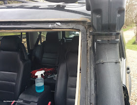
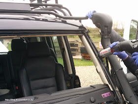
I drilled out the rivets and detached the plate from the A-pillar.


They had no trouble getting the trim off. They had far more trouble cutting through the sealant along the top and the side away from the raised air intake.

The most difficult part of refitting the screen was the upper edge trim that comes new with the screen. They admitted that Discovery screens are some of the more difficult that they have to do.


The technique for getting the A-pillar trim back on was to fit the clips to the plastic then clip that on to the body work. They started with the bottom clip but they had to align all of them in one go, near enough. It was a fiddle but the drivers side (UK) took far longer than the side with the snorkel!

Three of us worked on the offside. I held out the air intake as far as I dare without bending the wing panel. One held the bottom clip in place as the other person snapped in the other clips. The snorkel was not the tricky bit, just getting the clips aligned is what makes it hard.


There is a rubber strip attached which had to be pulled back out with a small hook once it was all clipped in.


They put in new trim clips and after they had gone I riveted back the support plate and re-attached the plastic pipe to that. Amazingly the originally holes lined up exactly.

==

This story does not end here, see the leak that followed!